Control Panel: Workcell
Public Unreviewedby Caleb
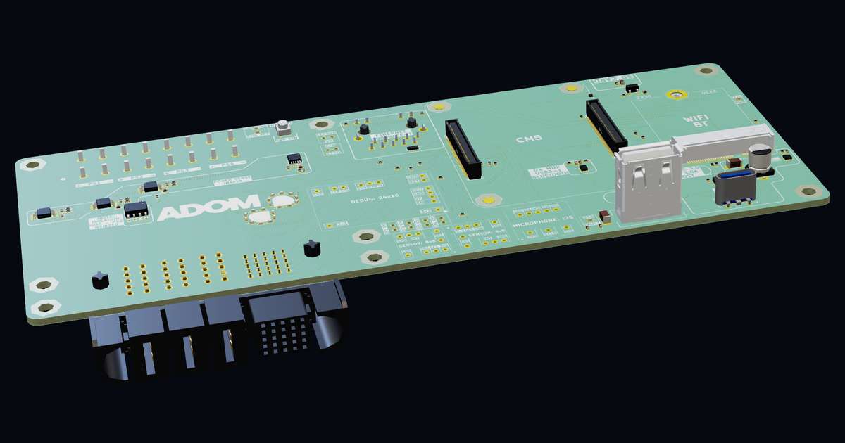
Control Panel: Workcell — Raspberry Pi CM5 carrier and smart power-distribution hub for Adom workcells. Four metered supply inputs (4× INA228, 20-bit) feed a switched, isolation-capable rail set delivered to the docked Control Panel: Scaffold over a Samtec ET60 blade dock with SWD/UART debug and RP2350 boot/reset control. On board: gigabit Ethernet, M.2 Wi-Fi + Bluetooth, USB-C/USB-A 3.0 with eFuse-protected VBUS, CAN FD, an 18-LED camera-feedback ring, and nested molecule slots for a PiProbe v1
3D Model
Contents
Control Panel: Workcell
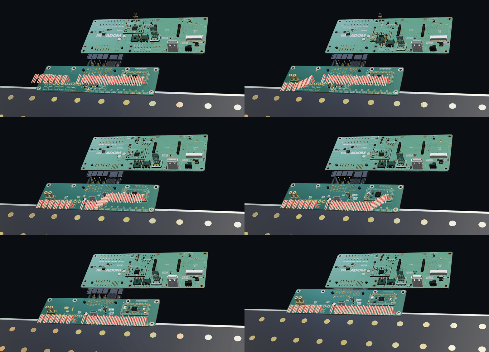
Mated system — Workcell + Scaffold
The full Control Panel pair mated coplanar at the ET60 dock, with every nested molecule, jumper, and wire dropping in:
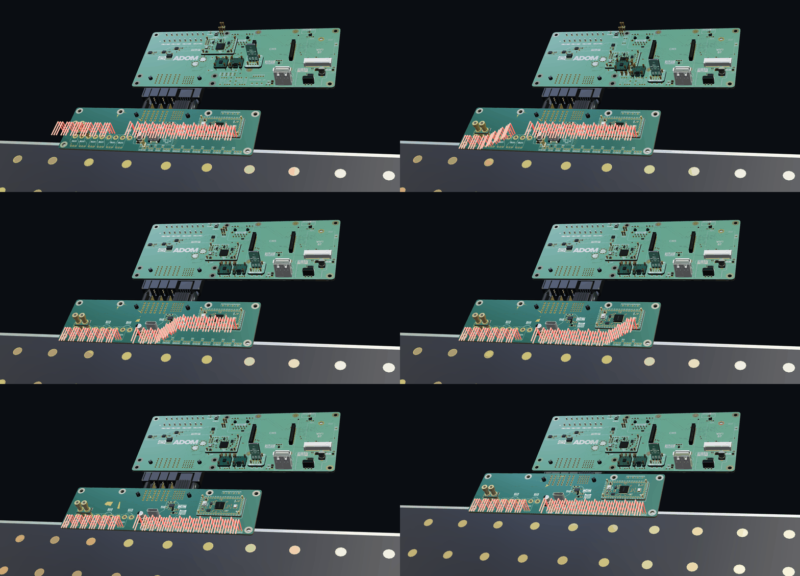 Raspberry Pi CM5 carrier and smart power-distribution hub for Adom workcells — the system half of the Control Panel pair. Four bench-supply inputs land on WAGO terminals, every rail is metered at 20-bit precision, and power + debug are delivered to the docked Control Panel: Scaffold through a Samtec ET60 blade dock. The board also carries the workcell's network, USB, CAN FD, wireless, sensing, and indicator infrastructure.
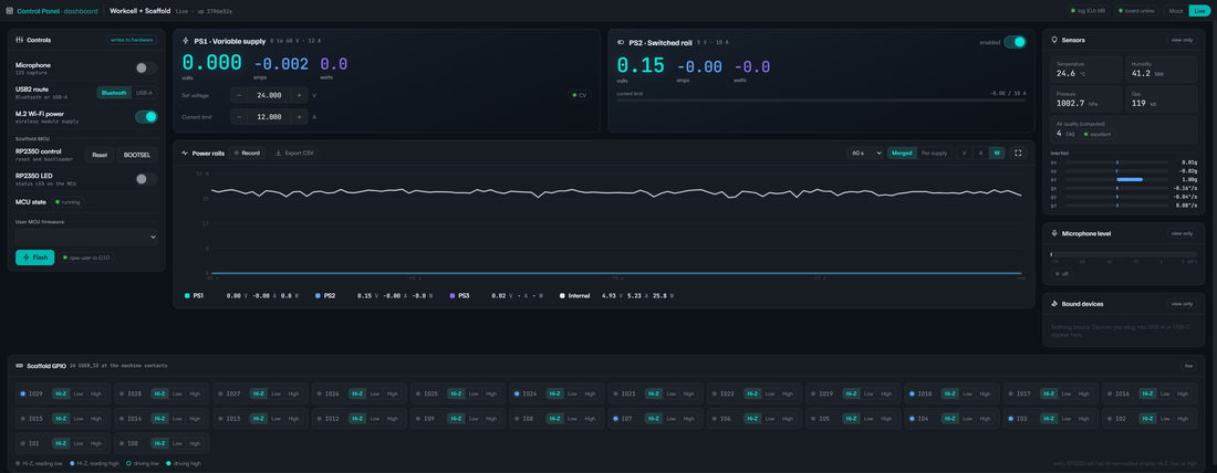
Companion App — Control Panel Dashboard
Like a TI EVM that ships with a companion GUI, this board comes with a companion dashboard app — bundled in this component's install package. Installing the component drops the app into place; run it and it talks to the board (over SSH here; USB on a bench tool) for live control + telemetry: meter all four rails, set PS1 like a bench supply, flip PS2 / M.2 / USB-mux, drive the scaffold GPIO, flash the RP2350, and run the ADOM ring light.
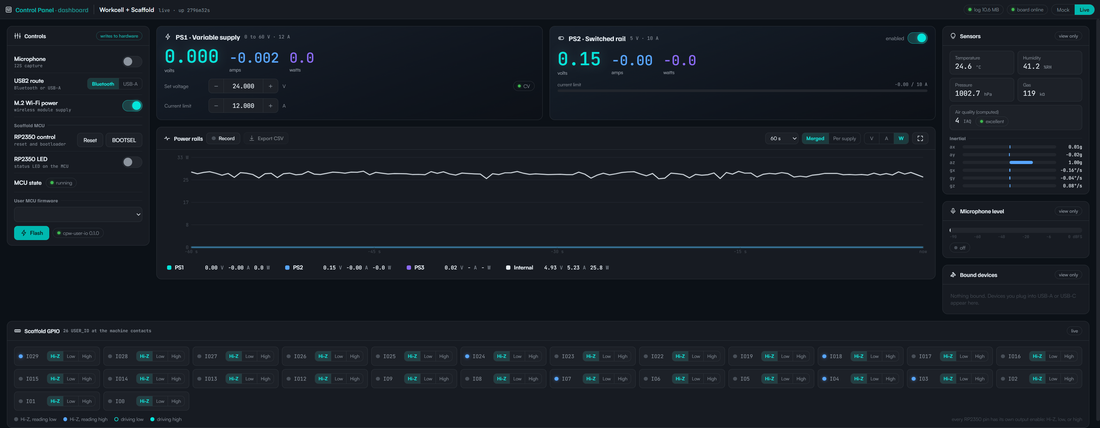
Get the companion app (the "installer" download — like a TI EVM's bundled GUI):
curl -L -o companion.tgz https://wiki.adom.inc/download/caleb/control-panel-workcell/2.0.24/companion-dashboard-app.tgz
tar xzf companion.tgz && bash run.sh        # serves the GUI on :8852, open via the container proxy URL
Full, installable app page: Control Panel Dashboard
(adom-wiki repo clone caleb/control-panel-dashboard). The app is versioned independently and
depends on this component, so the two travel together in the dependency graph.
How It Works
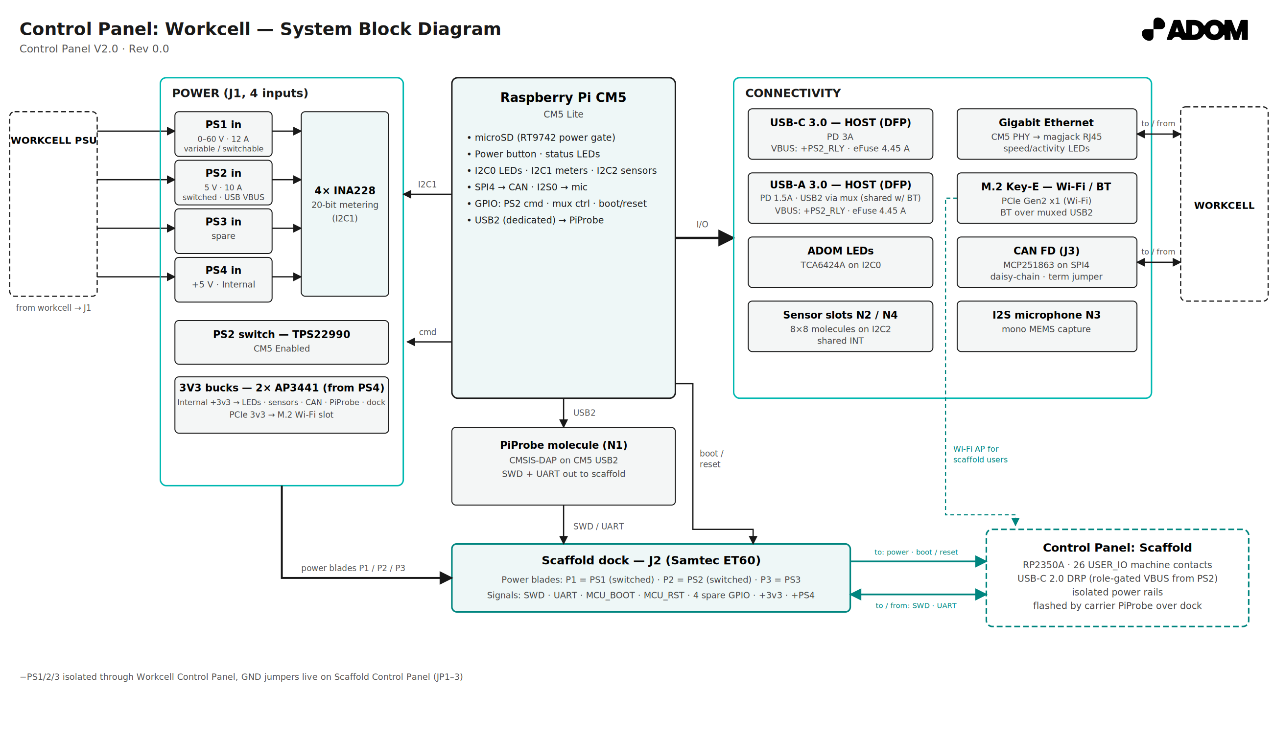
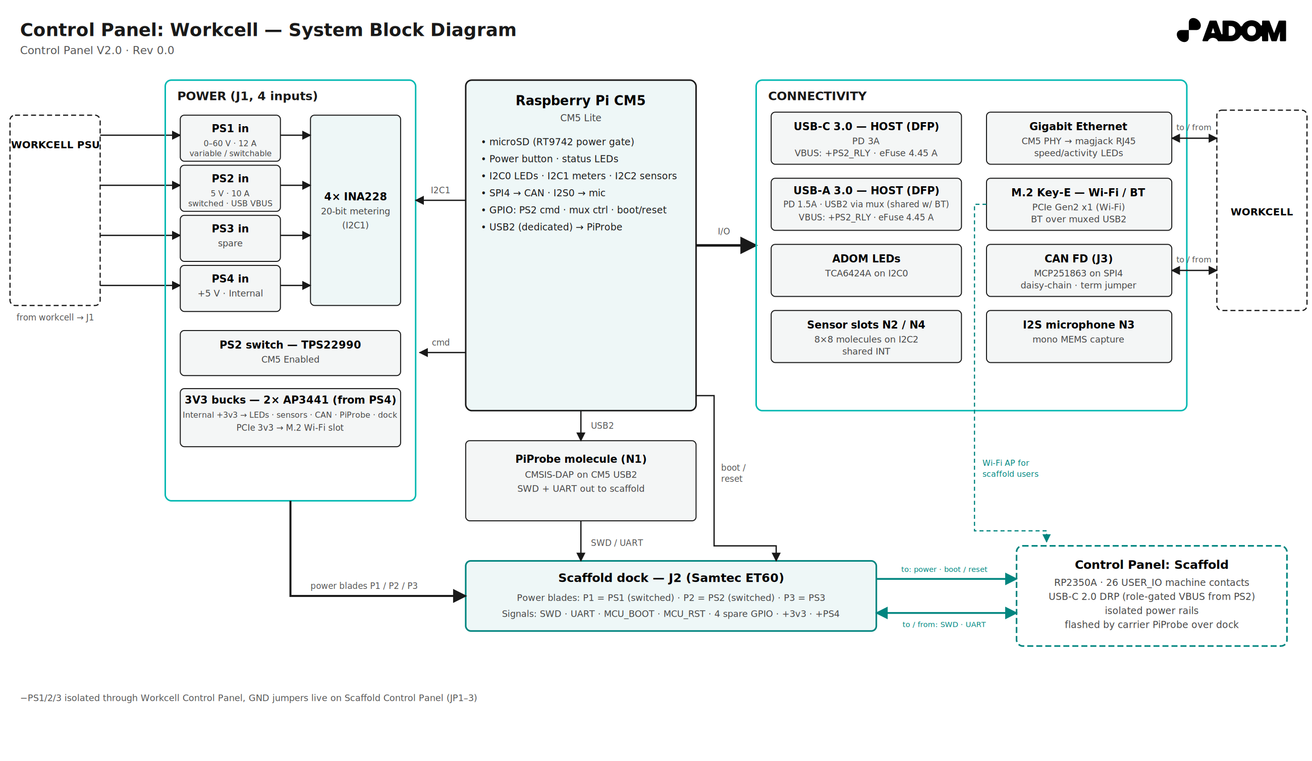
Power. Four independent inputs on J1 (WAGO 2604-1108, dual contacts per pole): PS1 (0–60 V / 12 A, user-variable), PS2 (5 V / 10 A), PS3 (spare), PS4 (5 V — powers this board and the CM5 through a 6.3 A fuse). Each rail is Kelvin-metered by its own INA228 (20-bit, ±0.05 %) on PWR_I2C-1. PS1–PS3 exit to the Scaffold on J2's power blades; PS2 is switched by the CM5 ("CM5 Enabled": CAM_GPIO1 → NSi8210 isolator → TPS22990 10 A load switch), and its isolated return may float ±2.5 V from common ground. Ground-scheme machine-pin jumpers bond GND to EGND when installed.
Compute. CM5 (Lite, microSD boot via an RT9742-gated Molex socket), power button + buffered power LED, EEPROM write-protect jumper. Headless — no HDMI/CSI/DSI.
Scaffold dock (J2, ET60S-S03). Three power blades (five contacts per polarity, separate returns) plus SWD/UART debug from the on-board PiProbe, MCU_BOOT/MCU_RST boot-strap control of the Scaffold RP2350, four spare CM5 GPIO (via JP1–JP4), and +3v3/+PS4 service rails.
Nested molecules (Adom standard slots). N1: PiProbe v1.3 debug probe on the CM5's dedicated USB2 port — the CM5 flashes the Scaffold RP2350 (and the probe itself) with stock openocd/picotool. N2/N4: 8×8 Bosch-standard sensor slots on SENSOR_I2C-2 + shared INT — fitted with BME690 (gas/T/RH/P) and BMI270 (IMU). N3: I2S MEMS microphone carrier on MIC_I2S-0.
Connectivity. Gigabit Ethernet (CM5 PHY → HR911130A magjack); M.2 Key-E for an AX210-class module (PCIe Gen2 x1 Wi-Fi + USB Bluetooth through a TMUXHS221 mux shared with USB-A's USB2 lanes — mutually exclusive); USB-C (SS via HD3SS3212 orientation mux, TUSB321 host/DFP, 3.0 A advertised) and USB-A 3.0, both VBUS-fed from PS2 through a TPS25940 eFuse; CAN FD (MCP251863 on SPI4) on daisy-chainable WAGO contacts with split-termination jumper JP6.
Indicators. TCA6424A expander (0x22, I2C0) drives an 18-LED blue ring for camera feed verification plus 4 status LEDs; RJ45 bezel LEDs are PHY-driven.
Overview
| Property | Value |
|---|---|
| Molecule ID | control-panel-workcell |
| Board | 172 × 72 mm, 6-layer |
| Compute | Raspberry Pi CM5 (Lite, microSD boot) |
| Power in | 4 rails on WAGO J1; 4× INA228 telemetry; PS2 switched + isolated |
| Dock out | Samtec ET60S-S03 → Control Panel: Scaffold (3 blades + 25 signals) |
| Nested slots | PiProbe v1.3 · BME690 · BMI270 · I2S mic carrier |
| Network | GbE, M.2 Wi-Fi (PCIe Gen2 x1), BT (USB), CAN FD |
| USB | USB-C (host, 3 A) + USB-A 3.0, eFuse-protected VBUS from PS2 |
| KiCad Version | 8 (7 hierarchical sheets) |
Companion Documents
All reved PDFs ship as downloadable assets on the board pages' releases (keeps the Files tab datasheet-free):
| Document | Purpose |
|---|---|
| Control Panel Functionality Overview | This board's function tables + CM5 pin tree |
| Scaffold Functionality Overview | The Scaffold-side companion overview |
| Workcell block diagram | System-side diagram, print form |
| Scaffold block diagram | Scaffold-side diagram |
| Control Panel Test Procedure | Full bring-up/test steps (§1–§8 are this board) |
| Control Panel Test Method Overview | Record sheet used with the procedure |
| Capabilities | Full engineering capability reference |
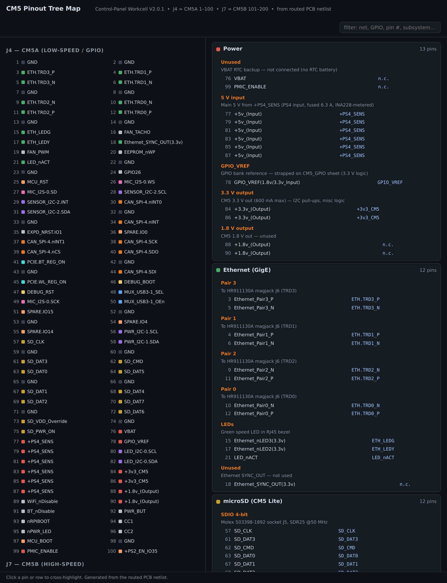
| CM5 Pinout Tree | All 200 CM5 pins (interactive, json) |
| Rev notes | Board revision history |
| Test explainers | ssh · stress step background |
| Companion zip | All PDFs, one download |
Connectors
| Ref | Part | Function |
|---|---|---|
| J1 | WAGO 2604-1108 | PS1–PS4 power input (dual contacts per pole) |
| J2 | Samtec ET60S-S03 | Scaffold dock — 3 power blades + 25 signals |
| J3 | WAGO 2060-452 | CAN FD (CANH/L, dual contacts for daisy-chain) |
| J4 / J7 | 100-pin board-to-board ×2 | CM5 socket |
| J5 | Molex 503398-1892 | microSD (RT9742 power-gated) |
| J6 | HR911130A | Gigabit Ethernet magjack |
| J8 | M.2 Key-E | Wi-Fi/BT module (AX210-class) |
| J9 | USB-A 3.0 | SS direct; USB2 via BT mux |
| J10 | USB-C | SS via orientation mux; host / DFP, 3.0 A |
Jumpers (small machine-pin fields)
| Ref | Function |
|---|---|
| JP1–JP4 | Spare CM5 GPIO (0 / 4 / 14 / 15) to the J2 dock — GPIO14/15 doubles as the Linux serial console |
| JP5 | CM5 EEPROM write-protect |
| JP6 | CAN split termination (open = unterminated) |
Key ICs
| Ref | Part | Function |
|---|---|---|
| U1–U4 | INA228 ×4 | 20-bit rail telemetry (PS4/PS3/PS2/PS1 @ 0x40/41/44/45) |
| U5 / U14 | AP3441 ×2 | +3v3 logic buck / M.2 3.3 V buck |
| U6 | NSi8210 | PS2 command isolator |
| U7 | TPS22990 | PS2 10 A load switch (3 ms slew) |
| U15 | MCP251863 | CAN FD controller + transceiver (40 MHz) |
| U16 | TCA6424A | 24-bit LED expander @0x22 |
| — | TPS25940 | USB VBUS eFuse (ILIM 4.45 A / OVP 5.68 V / UVLO 4.29 V) |
| — | HD3SS3212 / TMUXHS221 / TUSB321 | USB-C SS mux / BT-USB2 mux / CC controller |
3D Model / Bundle
Control_Panel_Workcell_v2.0.1.glb— OCCT conversion of the design-machine STEPcontrol-panel_workcell_v2.0.1.step/.kicad_pcb/.kicad_pro+ all 7 hierarchical.kicad_schsheets- JLCPCB BOM / CPL / gerbers
This board is the workcell dock base — it carries no MP anchor markers of its own (molecules dock onto it), so the GLB is a standard component conversion; wire-attach data for Hydrogen is generated from the board at import.
CM5 Pinout Tree — interactive
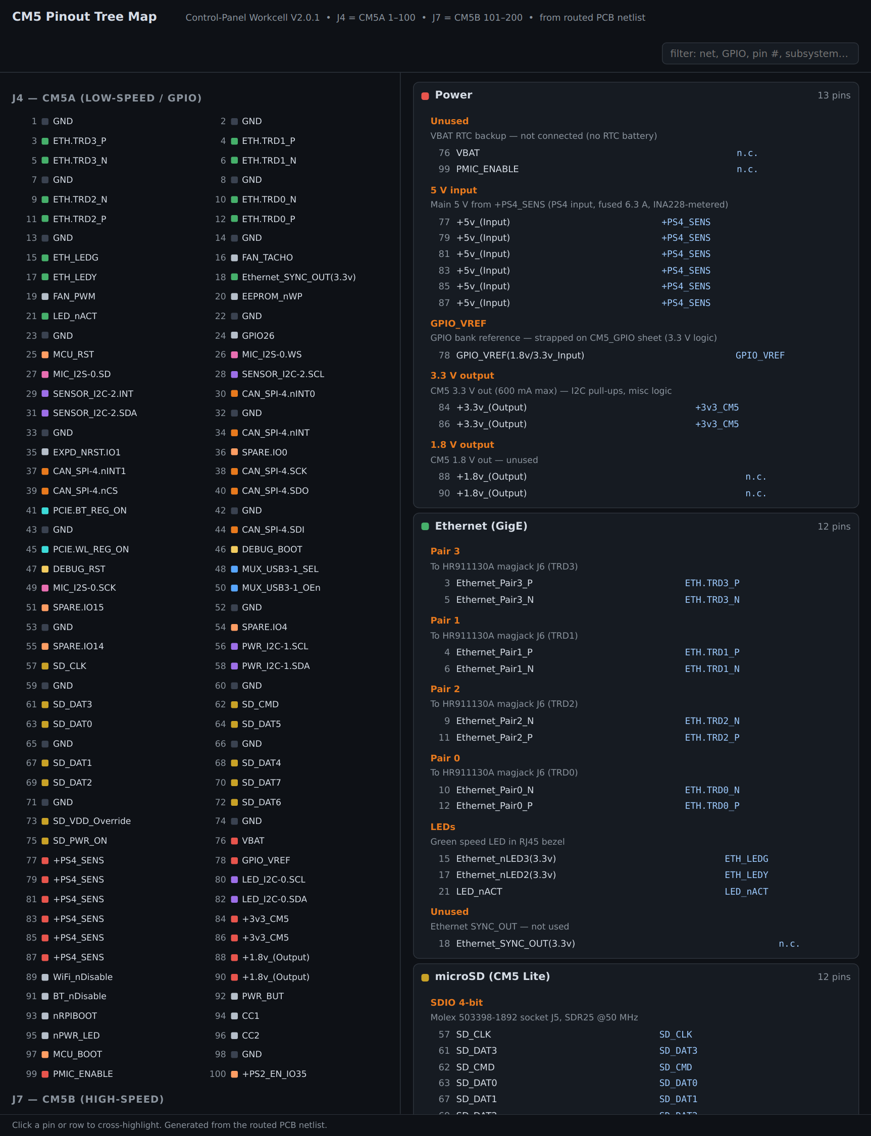
Open full screen · print form: CM5_Pinout_Tree.md
Import
adom-molecule create with --no-optimize reusing this GLB — do not regenerate from EDA export.