COSMIIC Implantables
Public Made by Adomby adom
The COSMIIC implantables factory project: a scaffold layout designed in the Hydrogen 3D editor (wireBender). Three eval frame molecules chained over the two-wire implant network bus beside a charging cluster on a 5x10 scaffold. Installing places wireBender.json into project-content/layouts for the 3

Contents
README
markdownCOSMIIC Implantables
The COSMIIC implantables factory project: a scaffold layout designed in the Hydrogen 3D editor, named wireBender, plus the node firmware that runs the bench. It places every COSMIIC eval module on Adom scaffolds and wires the implant network between them, so anyone picking up COSMIIC work can see the whole system, module by module, wire by wire, before touching a board.
Install
adom-wiki pkg install adom/cosmiic-implantables
The install copies wireBender.json into
$HOME/project/project-content/layouts/, the folder the 3D editor scans for
layouts, and the node firmware into project-content/firmware/. Open the 3D
Editor panel in Hydrogen and pick wireBender from the layout picker, or ask
the AI:
"open the cosmiic implantables layout in the 3D editor"
The scene
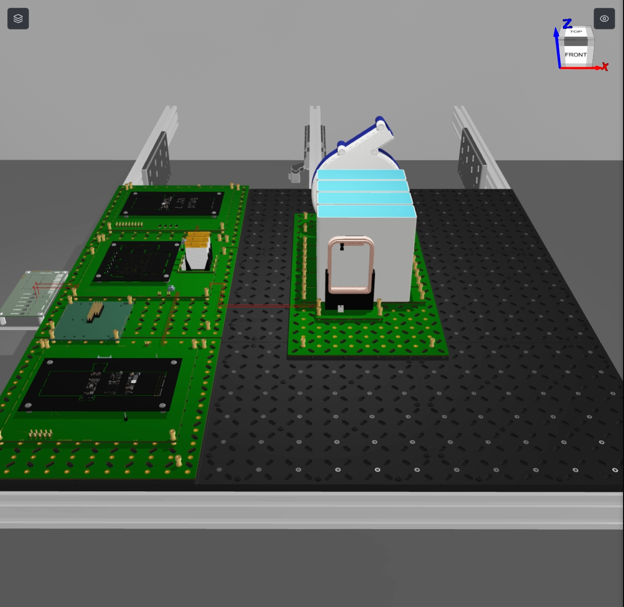
The bench splits into two halves:
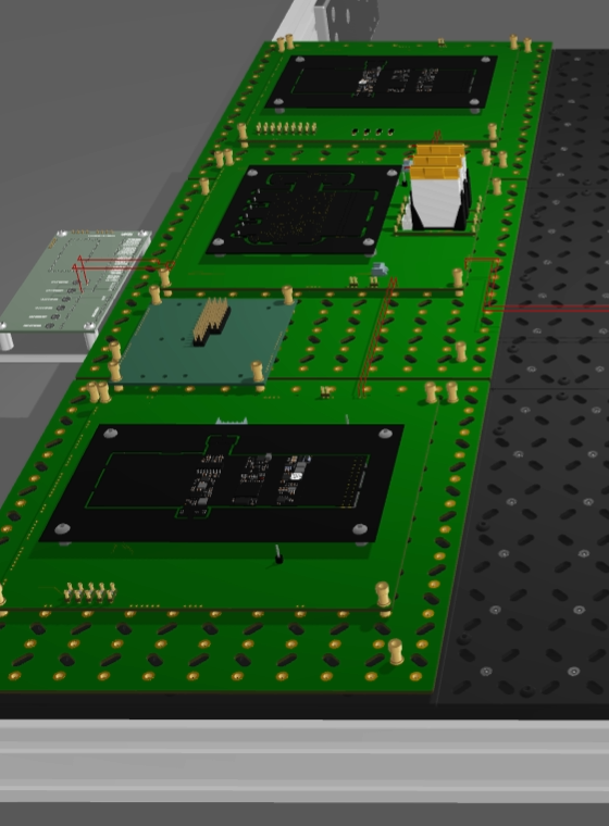
The network column (left) stacks three 6x6 scaffolds, each carrying one COSMIIC eval frame molecule: the PG4 pulse generator at the top, the PM1 power module in the middle, and the BP2 biopotential amplifier at the bottom. BUSA and BUSB wire pairs chain PG4 to PM1 and PM1 to BP2, mirroring the two-wire CAN-based implant network that connects COSMIIC modules in the body. A wireless link module sits beside the column, and two further wires run from PM1 to the control panel contacts X74 and X71.
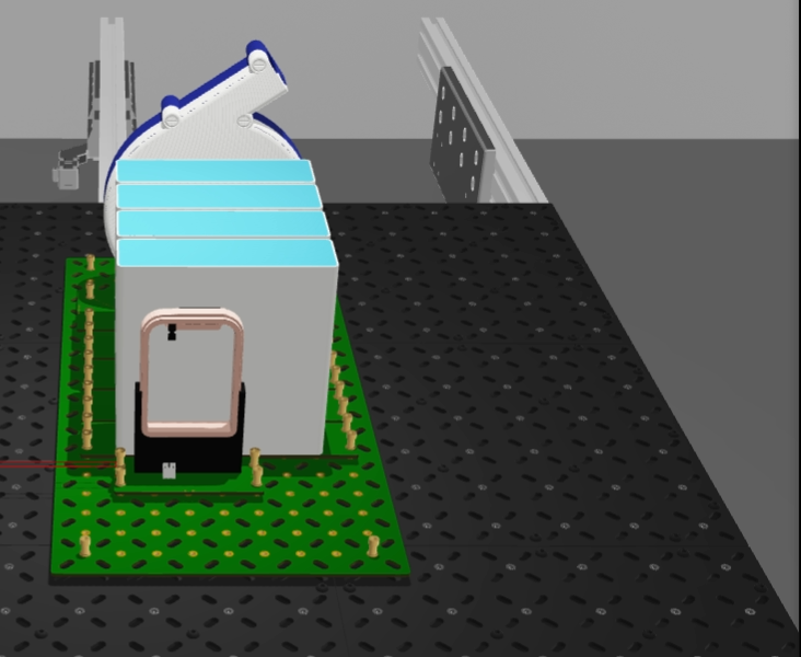
The charging cluster (right) sits on a 5x10 scaffold: the COSMOCOIL wireless charger, the PM charging coil wired to PM1's X1/X2 coil contacts, and four adipose spacer molecules that stand in for tissue between coil and module during charging tests.
Firmware
Two node images ship with the project and install into
project-content/firmware/:
pg4-stim-node-v0.3.2.uf2: stimulation node on the PG4 eval framepm1-power-node-v0.1.7.uf2: power management node on the PM1 eval frame
Flash them to the eval frames (UF2 drag-and-drop or picotool) before running the bench.
Bill of molecules
14 instances of 9 molecules. Every one is a declared dependency of this project:
| Molecule | Qty | Role |
|---|---|---|
| pg4-frame-mol | 1 | PG4 pulse generator eval frame |
| pm1-frame-mol-refined | 1 | PM1 power module eval frame |
| bp2-frame-mol | 1 | BP2 biopotential amplifier eval frame |
| lrg-lrg-6x6-p16 | 3 | 6x6 scaffolds under the network column |
| lrg-lrg-5x10-p16 | 1 | 5x10 scaffold under the charging cluster |
| cosmocoil-mol | 1 | COSMOCOIL wireless charger |
| pm-coil-molecule | 1 | PM charging coil |
| adipose-molecule | 4 | Tissue-equivalent spacers |
| wireless-link | 1 | Wireless link module |
The 8 wires are all 24 AWG: two BUSA/BUSB pairs for the network chain, the X1/X2 coil pair between the PM coil and PM1, and the two control panel runs.
Files
wireBender.json: the layout itself (molecules and wires, editable with the adom-layouts spec or straight from the 3D editor).firmware/*.uf2: the node images installed toproject-content/firmware/.install.sh/uninstall.sh: copy the layout and firmware into place and remove them again. Both preserve local edits: install backs up a modified layout towireBender.json.bak, uninstall leaves a modified file in place.SKILL.md: teaches the AI to open and explain the layout.