Fusion - the Fusion 360 Bridge
Public Made by Adomby adom
Drive Autodesk Fusion 360 from the cloud via Adom Bridge: component libraries, IPC package generation, board layout, exports (STEP/Gerbers/BOM/CPL), fast APS cloud search, and parametric modeling.
Electronics library manager
Building and maintaining Fusion Electronics libraries: symbols, footprints, and real 3D packages, generated rather than hand-drawn.
What a library part needs
A usable Adom part is three things that must agree with each other:
- a symbol (schematic)
- a footprint (the pads the part solders to)
- a 3D package (what it looks like on the board)
Get the third one misaligned and the board renders wrong; get the second wrong and it does not solder.
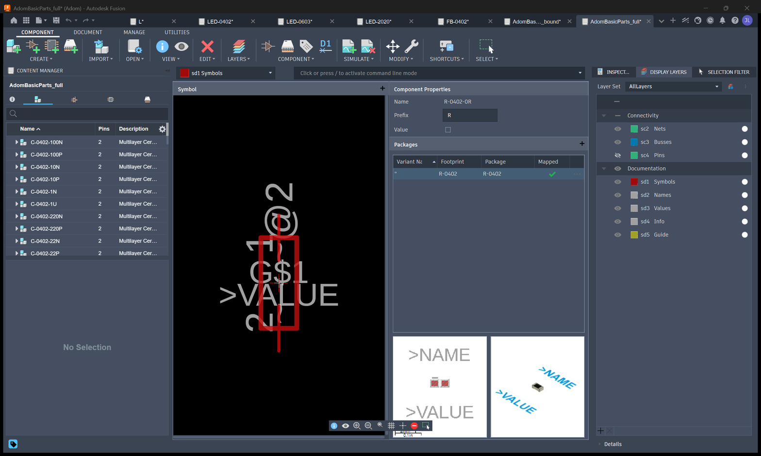
The whole 138-part Adom basic parts library open in Fusion's library manager: the component list on the left, and each part carrying its symbol, footprint and 3D package.
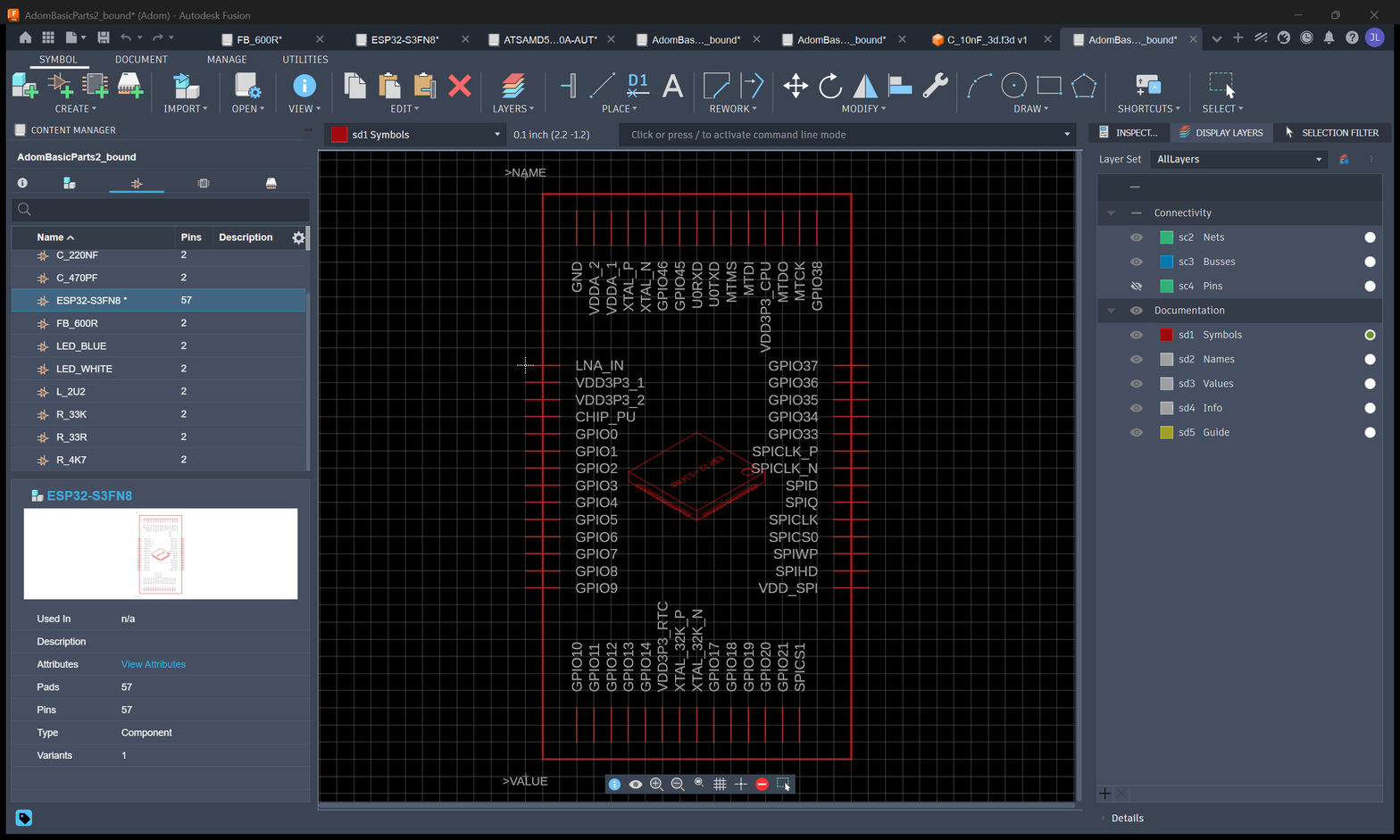
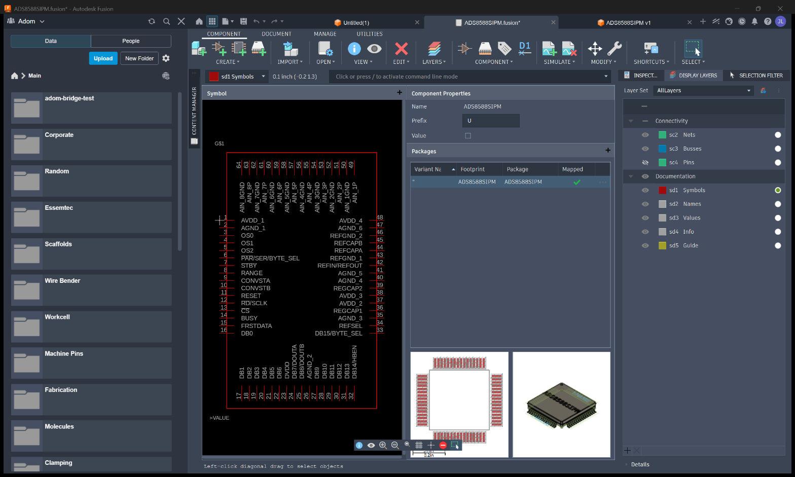
The three views an EE checks for a single part, here the schematic symbol (full pinout) and the footprint with its pad stack:
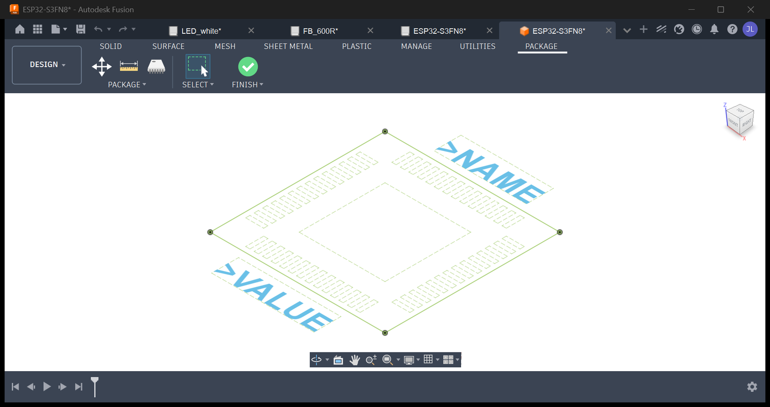
And a 3D package bound to its footprint, the check that catches a misaligned part before it ever reaches a board:
Opening and inspecting
adom-desktop fusion_open_lbr '{"lbrPath":"C:/tmp/AdomBasicParts.lbr"}'
.lbr is the EAGLE library format Fusion Electronics uses.
Generating packages
adom-desktop fusion_generate_package '{"package":"R_4k7", ...}'
fusion_generate_package builds a parametric IPC package, including laser-etched markings, rather
than drawing pads by hand. IPC-derived geometry is what keeps footprints consistent across a
library.
3D packages
adom-desktop fusion_make_3d_package   '{...}'      # build one
adom-desktop fusion_attach_3d_package '{...}'      # bind it to a footprint
adom-desktop fusion_build_library_3d  '{"lbrPath":"C:/tmp/newlib/AdomBasicParts2.lbr",
                                        "parts":[{"package":"R_4k7",
                                                  "lbrPath":"C:/tmp/newlib/R_4k7.lbr",
                                                  "modelPath":"C:/tmp/newlib/R_4k7.step"}]}'
adom-desktop fusion_capture_library_views '{...}'  # render views for a wiki page
fusion_build_library_3d is the batch path: hand it a list of parts with their STEP models and it
binds 3D to each package in one pass, returning per-part success plus screenshots.
The auto-orient rule
Auto-orient used to rotate the smallest bounding-box dimension to Z. That is correct for a flat SMD chip and badly wrong for a tall through-hole machine pin, which ended up lying on its side.
Tall parts now stay vertical: if dz is already the largest dimension, the part is left alone and
only flat SMD parts get tipped. If you are adding a part type with unusual proportions, check the
3D orientation before committing it to a library.
Verifying a part before you commit it
A part that is subtly wrong is worse than a missing one, because it silently produces bad boards. Check:
- Pin 1 is where the footprint says it is.
- The seat plane is at z=0, so the part sits on the board rather than floating or sinking.
- The 3D body's footprint matches the pad geometry.
The adom-chipfit tool exists for exactly this and validates a 3D chip GLB against its
.kicad_mod: pin-1 alignment, package-family guard, seat-plane delta-z and size match.
Publish the whole part
When a component gets a wiki page, publish everything: symbol, footprint, 3D model, the source
.lbr, and the STEP. Someone else's board depends on being able to use the part, not just look at
it.
Related
- 3D board view and export for the GLB pipeline these models feed.
- 2D board layout for how footprints become manufacturing output.
# Electronics library manager
Building and maintaining Fusion Electronics libraries: symbols, footprints, and real 3D packages,
generated rather than hand-drawn.
## What a library part needs
A usable Adom part is three things that must agree with each other:
1. a **symbol** (schematic)
2. a **footprint** (the pads the part solders to)
3. a **3D package** (what it looks like on the board)
Get the third one misaligned and the board renders wrong; get the second wrong and it does not
solder.
The whole 138-part Adom basic parts library open in Fusion's library manager: the component list on
the left, and each part carrying its symbol, footprint and 3D package.

The three views an EE checks for a single part, here the schematic **symbol** (full pinout) and the
**footprint** with its pad stack:


And a **3D package bound to its footprint**, the check that catches a misaligned part before it ever
reaches a board:

## Opening and inspecting
```bash
adom-desktop fusion_open_lbr '{"lbrPath":"C:/tmp/AdomBasicParts.lbr"}'
```
`.lbr` is the EAGLE library format Fusion Electronics uses.
## Generating packages
```bash
adom-desktop fusion_generate_package '{"package":"R_4k7", ...}'
```
`fusion_generate_package` builds a parametric IPC package, including laser-etched markings, rather
than drawing pads by hand. IPC-derived geometry is what keeps footprints consistent across a
library.
## 3D packages
```bash
adom-desktop fusion_make_3d_package '{...}' # build one
adom-desktop fusion_attach_3d_package '{...}' # bind it to a footprint
adom-desktop fusion_build_library_3d '{"lbrPath":"C:/tmp/newlib/AdomBasicParts2.lbr",
"parts":[{"package":"R_4k7",
"lbrPath":"C:/tmp/newlib/R_4k7.lbr",
"modelPath":"C:/tmp/newlib/R_4k7.step"}]}'
adom-desktop fusion_capture_library_views '{...}' # render views for a wiki page
```
`fusion_build_library_3d` is the batch path: hand it a list of parts with their STEP models and it
binds 3D to each package in one pass, returning per-part success plus screenshots.
### The auto-orient rule
Auto-orient used to rotate the **smallest** bounding-box dimension to Z. That is correct for a flat
SMD chip and badly wrong for a tall through-hole machine pin, which ended up lying on its side.
Tall parts now stay vertical: if `dz` is already the largest dimension, the part is left alone and
only flat SMD parts get tipped. If you are adding a part type with unusual proportions, check the
3D orientation before committing it to a library.
## Verifying a part before you commit it
A part that is subtly wrong is worse than a missing one, because it silently produces bad boards.
Check:
- **Pin 1** is where the footprint says it is.
- The **seat plane** is at z=0, so the part sits on the board rather than floating or sinking.
- The 3D body's footprint **matches the pad geometry**.
The `adom-chipfit` tool exists for exactly this and validates a 3D chip GLB against its
`.kicad_mod`: pin-1 alignment, package-family guard, seat-plane delta-z and size match.
## Publish the whole part
When a component gets a wiki page, publish everything: symbol, footprint, 3D model, the source
`.lbr`, and the STEP. Someone else's board depends on being able to use the part, not just look at
it.
## Related
- [3D board view and export](3d-viewer-and-export.md) for the GLB pipeline these models feed.
- [2D board layout](board-layout-2d.md) for how footprints become manufacturing output.