Adom Library
Public Made by Adomby adom
adom-lbr — the EDA library translator. Bring a component in from any supported EDA tool and convert it to any other (KiCad ⇄ Altium ⇄ EAGLE/Fusion) through one canonical adom-lbr JSON — symbol + footprint + 3D + pin↔pad map. Altium is written natively (no Altium needed). Includes the adom-lbr Manager: browse wiki components and view symbol/footprint/3D + the per-EDA layer stackup.
| Name | Last updated |
|---|---|
| footprint-4sided.png | 3mo ago |
| hints.png | 3mo ago |
| README.md | 3mo ago |
| SKILL.md | 1mo ago |
| symbol-art-faithful.png | 3mo ago |
| symbol-art-gallery.png | 3mo ago |
| symbol-art-hints.png | 3mo ago |
| symbol-art-sizing.png | 3mo ago |
| symbol-art-transcribe.png | 3mo ago |
| viewer3col.png | 3mo ago |


Fusion 360 library export — a field guide
A sub-skill of adom-lbr. This is the human-readable walkthrough; the agent-facing rules live in SKILL.md right next to it.
Turning a KiCad part into a Fusion 360 library looks like one command — but
there are four places it quietly goes wrong. This guide is how to get a library
that places with the real footprint and a rendered 3D body, every time.
The same .lbr also imports into Altium and OrCAD.
What "right" looks like
A correct export gives you all three faces of the part — schematic symbol, the real footprint, and the 3D body — tied together by a complete pin→pad map:
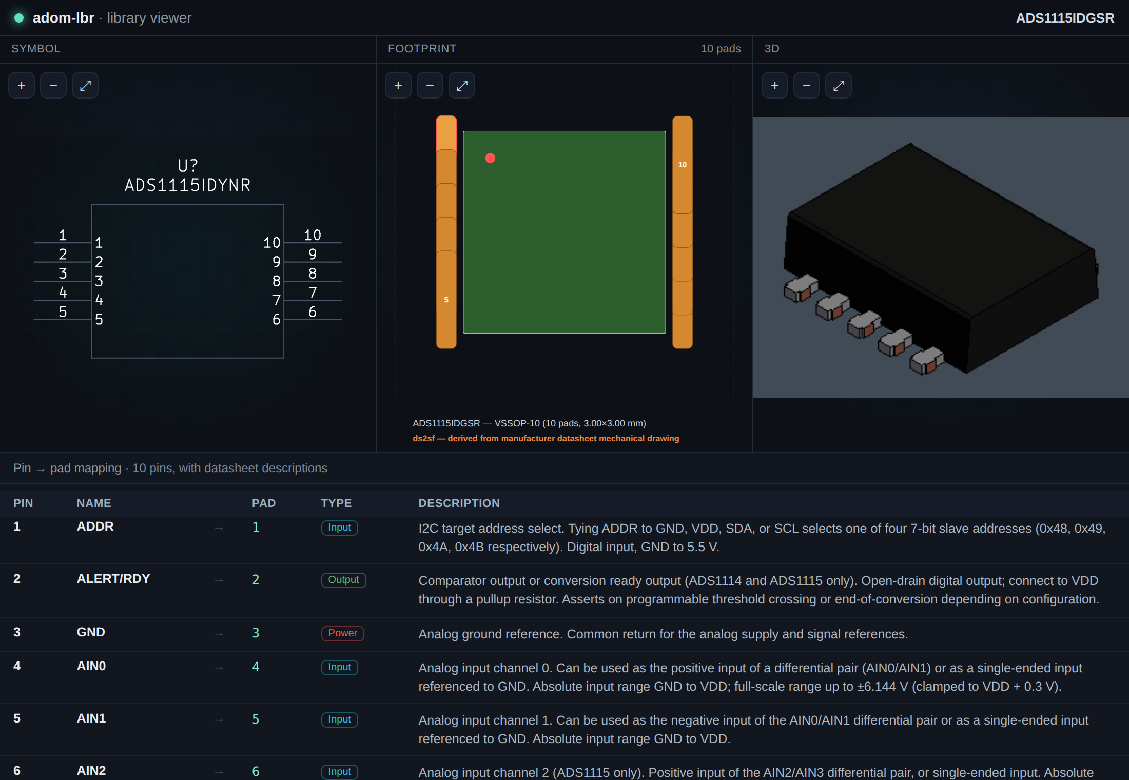
Trap #1 — the footprint must come from the real .kicad_mod
Pass --fp. Without it, every pad is dumped into two columns and a 4-sided LQFP
comes out as a domino — wrong pads, wrong sizes, wrong rotations. With it, pads
land in their true positions (a real ADS8588SIPM LQFP-64: 16 per side):
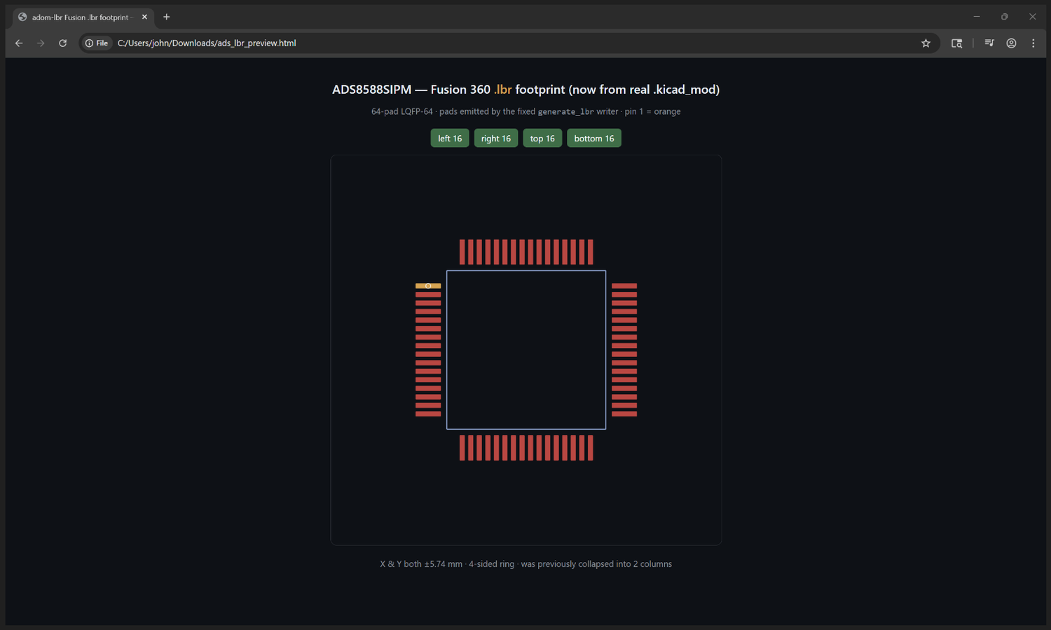
The tool warns you in-band
You don't have to remember these traps — adom-lbr surfaces them as hints at the
moment of use (it knows agents barely read skills). Forget --fp and it says so,
loudly; use it and it confirms the real geometry and points at the next step:
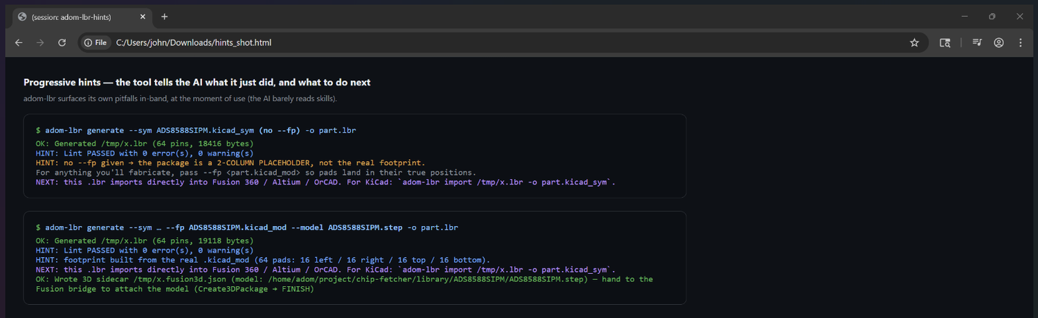
The other three traps (short version)
- 3D is a Fusion-side attach, not a flat-file write. The body only renders
once Fusion brings the model into a session. The bridge does
Create3DPackage → import → orient → FINISH → Save(binds and renders);--modeljust emits the sidecar that points it at the model. - Self-hosted models link by
wip_urn(urn:adsk.wipprod:fs.file:vf.<id>?version=N, withurn=""), noturn:adsk.eagle:package(that's managed/library.io only). - Never put a
dm.lineageURN in the.lbr— Fusion pins the versionedfs.fileURN; keepdm.lineageas sidecar provenance only.bind-3drefuses it.
The flow — who does what
| Step | Who | Command / action |
|---|---|---|
Generate 2D .lbr + sidecar |
adom-lbr | generate --sym … --fp … --model part.step |
| Attach 3D (binds and renders) | Fusion bridge | Create3DPackage → import → orient → FINISH → Save |
| Report the minted URN | Fusion bridge | fusion_aps_file_info {query:"<package>"} → fs.file:vf…?version=N |
| Record URN back (provenance) | adom-lbr | bind-3d --record-only --sidecar … --wip-urn <that> |
(Optional) bake binding into .lbr |
adom-lbr | bind-3d --lbr part.lbr --wip-urn <that> |
The in-Fusion library is the runtime source of truth; the sidecar is adom-lbr-owned bookkeeping.
Quick triage
| Symptom | Fix |
|---|---|
| Footprint is two columns / a domino | regenerate with --fp part.kicad_mod |
| Fusion: "No Components" | adom-lbr lint part.lbr → fix the reported code |
| 3D body is a gray placeholder | let the bridge attach it (Create3DPackage → FINISH) |
bind-3d rejected the URN |
self-uploaded → --wip-urn; managed → --urn |
| 3D offset / wrong pin 1 | run chipfit; set placement in the sidecar before FINISH |
Drawing the 3D chip outline onto the symbol — --symbol-art
adom-symbol does a lot of work to produce a vector line-drawing of the chip
(<mpn>-3d-outline-*.svg). --symbol-art puts that drawing on the schematic
symbol, so the part shows a little picture of itself in Fusion / Altium / OrCAD.
adom-lbr generate --sym part.kicad_sym --fp part.kicad_mod \
  --symbol-art part-3d-outline.svg -o part.lbr
Every outline adom-symbol can create — the --symbol-art inputs
adom-symbol emits the outline in several variants. bold / thin / dark / teal are
the same drawing (a silhouette + the front lead banks) in four stroke styles —
since adom-lbr transcribes geometry, they land identically on the symbol.
blueprint is the full iso wireframe (every edge). -named adds the
part-name text. Pick by detail + weight; pass whichever you want:
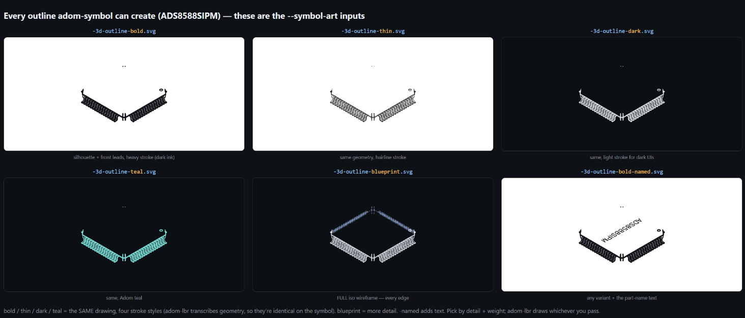
The format — SVG polylines → EAGLE wires
The outline SVGs are already flattened polylines (no beziers) in a 320×320 pixel space. adom-lbr transcribes them into the symbol:
- each
<polyline>/<polygon>point-run → a chain of EAGLE<wire>s on layer 94, - SVG is Y-down, EAGLE is Y-up → Y is negated,
- the drawing is decimated (dense curve sampling collapsed) and centred + scaled to the symbol body.
Is the translation faithful? (overlay test)
Here's the honest check — adom-symbol's source outline, adom-lbr's wires on the symbol, and the two overlaid (gray = source, teal = mine) at matched scale. The teal sits right on the gray for both the standard and the detailed blueprint outline; decimation smooths it a hair but the shape holds:
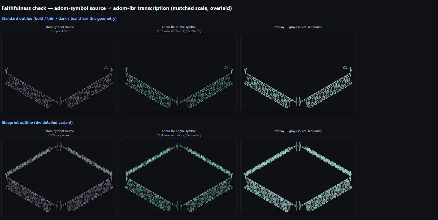
- Standard (783 polylines) → ~1,150 wire segments.
- Blueprint (2,246 polylines) → ~2,980 wire segments.
- Named carries the part-name text through too.
The single biggest faithfulness lever is scale: at the small symbol size the
decimation tolerance eats fine detail, so a denser outline on a tiny symbol loses
the most. Pass a larger --symbol-art-scale (or a simpler variant) if you want
every line crisp.
Matching adom-symbol's size (the iterations)
adom-symbol sizes the outline to a small centred icon (~⅓ of the body) so it doesn't crowd the pins/labels. The first pass drew it too big; tuning the fit to 0.38× the body's smaller side matches adom-symbol's own placement:
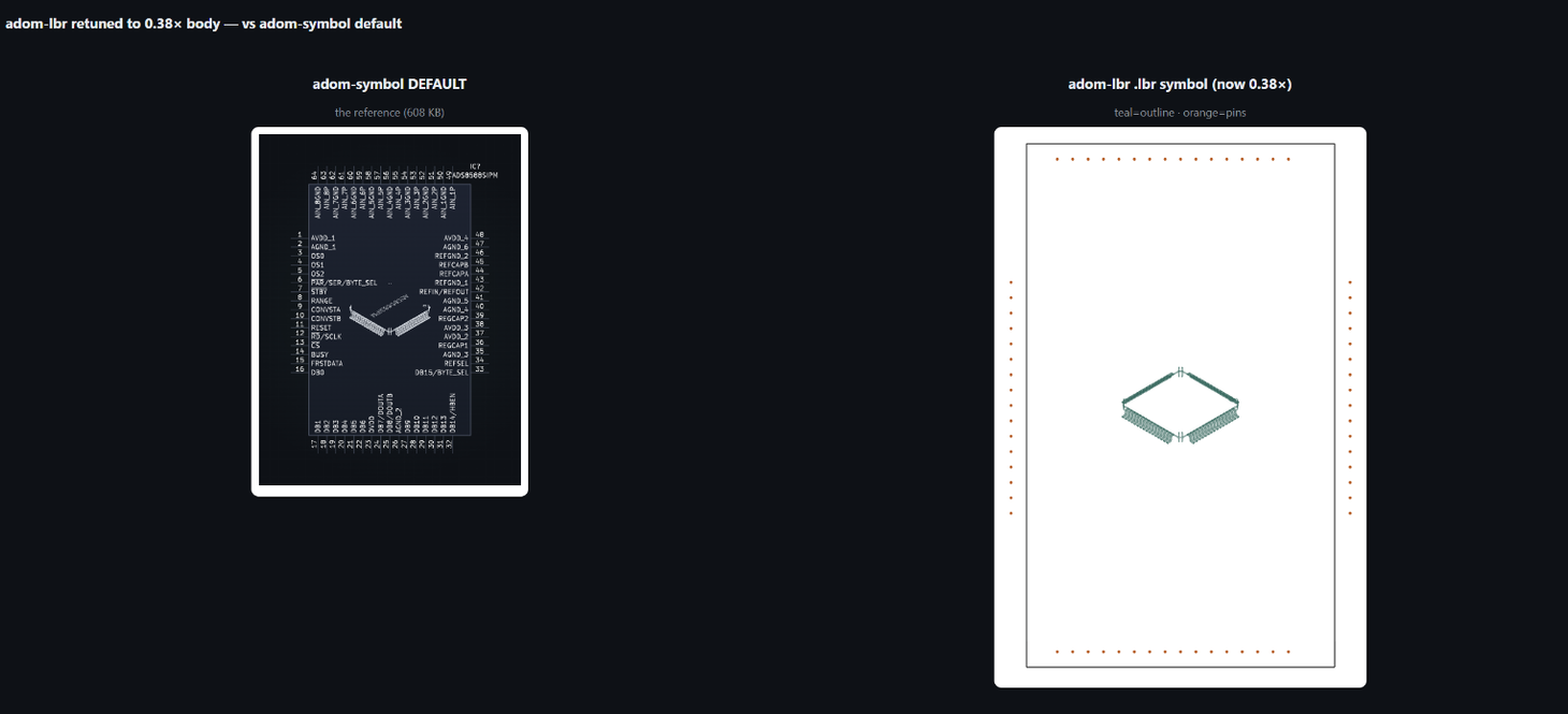
Standing rule: always match what adom-symbol gives you as closely as you can. If the match drifts, the real fix is a tighter contract from adom-symbol (emit the outline already in symbol mm-space). See ../../docs/ROADMAP.md.
Tune per-part with --symbol-art-scale <frac> (default 0.38; higher = bigger).
Pitfall — a too-detailed outline bloats the library
A detailed outline is a lot of wires. The -blueprint variant ≈ 3000 <wire>s
/ ~300 KB for one part — that bloats the .lbr and can lag Fusion's symbol
editor. So the tool warns the AI in-band and tells it to pass a simpler outline:
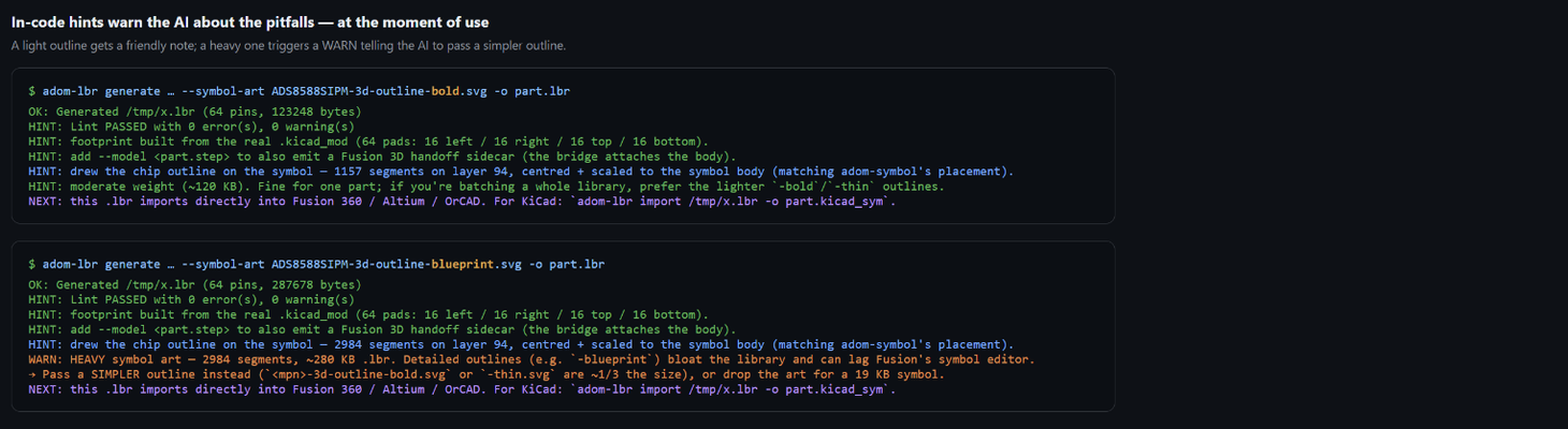
Rule of thumb: -bold / -thin (~120 KB) for normal use or batching a whole
library; -blueprint (~300 KB) only when you want the full iso wireframe on one
showcase part.
Commands the AI can call
# default look (matches adom-symbol, light outline)
adom-lbr generate --sym P.kicad_sym --fp P.kicad_mod --symbol-art P-3d-outline-bold.svg -o P.lbr

# bigger icon
adom-lbr generate --sym P.kicad_sym --fp P.kicad_mod --symbol-art P-3d-outline-bold.svg --symbol-art-scale 0.55 -o P.lbr

# full detail (heavy — only when you want it)
adom-lbr generate --sym P.kicad_sym --fp P.kicad_mod --symbol-art P-3d-outline-blueprint.svg -o P.lbr
Sample prompts (what a user says → what the AI runs)
- "Make a Fusion library for this part and put the chip drawing on the symbol."
→
generate --fp … --symbol-art <mpn>-3d-outline-bold.svg - "The chip picture on the symbol is too big." → re-run with
--symbol-art-scale 0.3. - "My .lbr is huge / the symbol editor is laggy." → the heavy-art WARN already told you:
swap
-blueprintfor-bold/-thin, or drop--symbol-art. - "Match adom-symbol exactly." → use adom-symbol's outline SVG as
--symbol-art; for a pixel-exact match, ask adom-symbol for the mm-space outline (see ROADMAP).
→ Agent-facing rules: SKILL.md. The app, full CLI, and live 3-column viewer: adom/adom-lbr.