SMI230 — 6DoF Inertial Sensor for Automotive Applications
UnreviewedRobert Bosch GmbH SMI230. Automotive-grade 6-axis IMU combining 16-bit triaxial accelerometer and gyroscope in LGA-16 package. AEC-Q100 Grade 2, SPI/I2C, 2.4-3.6V. 106-page full datasheet with all 41
Symbol & Footprint
PCB Footprint

Source: Bosch Technical Product Description (V2.1, Feb 2022)
Manufacturer: Robert Bosch GmbH
Part Number: SMI230 (0273 142 144)
Document: Technical Product Description V2.1 — Feb 2022
Description
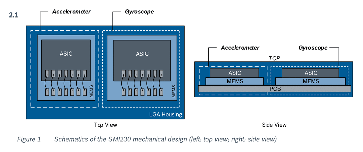
The SMI230 is a combined triaxial accelerometer and triaxial gyroscope (6 degrees of freedom) for non-safety automotive applications such as in-dash navigation. It is based on a two-chip stacked concept: the accelerometer and gyroscope sensing elements (MEMS) are mounted side-by-side, with read-out ASICs stacked on top of each respective sensing element, all within a single LGA-16 package.
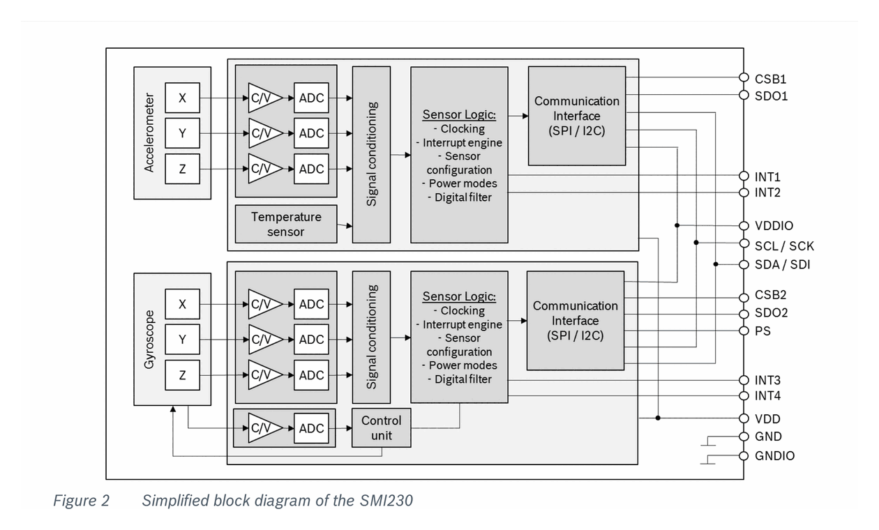
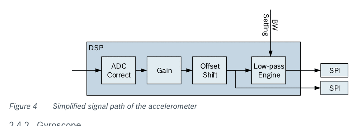
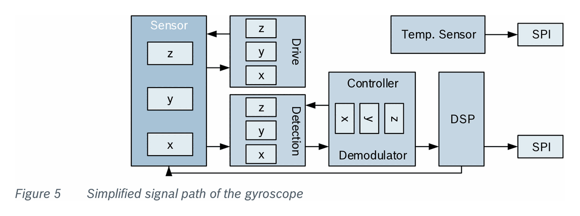
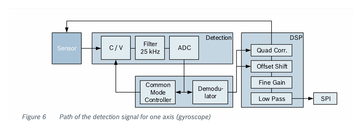
The accelerometer detects differential capacitance changes from comb-like seismic masses suspended on silicon spring bars. The gyroscope uses the Coriolis vibratory principle with two seismic masses oscillating at ~25 kHz via electrostatic drive forces. Both sensors feed through hybrid analog-digital converters (ADCs) at 400 kHz sampling rate into digital signal processors (DSPs) with configurable low-pass filtering, gain, and offset correction.
The gyroscope and accelerometer can be operated individually or tied together for data synchronization. The device supports SPI (up to 10 MHz) and TWI/I2C (up to 400 kHz) interfaces with separate chip selects for each sensor.
Key Specifications
| Parameter | Value |
|---|---|
| Supply Voltage (VDD) | 2.4V to 3.6V |
| I/O Supply Voltage (VDDIO) | 1.62V to 3.6V |
| Supply Current (ACC normal) | 170 uA typ |
| Supply Current (GYR normal) | 5 mA typ |
| Supply Current (ACC suspend) | 3 uA typ |
| Supply Current (GYR deep suspend) | <5 uA typ |
| Operating Temperature | -40 to +105 degC |
| Interfaces | SPI (10 MHz max), TWI/I2C (400 kHz max) |
| Package | LGA-16 (3.0 x 4.5 x 0.95 mm) |
| Weight | 27.48 mg |
| Accelerometer Ranges | +/-2, +/-4, +/-8, +/-16 g |
| Gyroscope Ranges | +/-125, +/-250, +/-500, +/-1000, +/-2000 deg/s |
| Data Resolution | 16-bit (accelerometer and gyroscope) |
| Qualification | AEC-Q100 Grade 2 |
| ESD Protection | 2 kV HBM |
Features
- Combined 16-bit triaxial accelerometer and 16-bit triaxial gyroscope in a single package
- Accelerometer and gyroscope operable individually or synchronized via data synchronization feature
- Selectable measurement ranges: +/-2/4/8/16 g (accel), +/-125/250/500/1000/2000 deg/s (gyro)
- Configurable low-pass filter bandwidth with bypass option
- On-chip FIFO buffers for both accelerometer and gyroscope
- Configurable interrupt engine: any-motion, no-motion, high-g, low-g, orientation detection
- On-chip temperature sensor (-104 to +150 degC, 11-bit, 0.125 K/LSB)
- SPI and TWI/I2C digital interfaces with separate chip selects
- Power-on reset (POR) generator
- 5 power modes per sensor (normal, suspend, deep suspend for gyro)
- Self-test capability for both sensors
- AEC-Q100 Grade 2 qualified, MSL1, RoHS compliant, halogen-free
- Mechanical shock tolerance up to 10,000 g (duration <=200 us)
- Application support software and config file upload capability
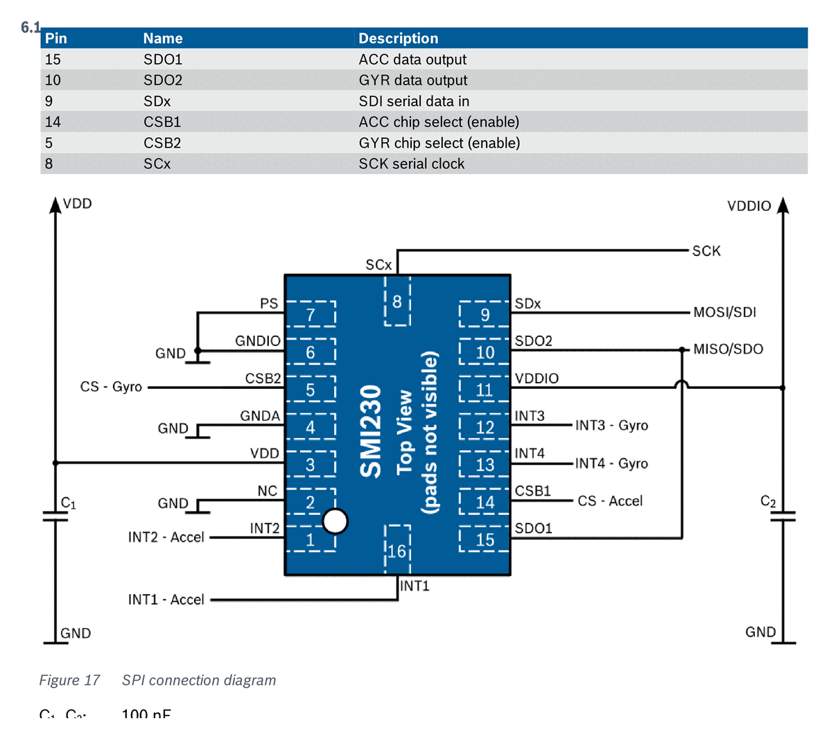
Pin Configuration
| Pin | Name | Type | Description |
|---|---|---|---|
| 1 | INT2 | Digital I/O | Interrupt pin (ACC #2) |
| 2 | NC | -- | Not connected (tie to GND) |
| 3 | VDD | Supply | Power supply analog and digital domain |
| 4 | GNDA | Ground | Ground for analog domain |
| 5 | CSB2 | Digital In | SPI chip select gyroscope |
| 6 | GNDIO | Ground | Ground for I/O |
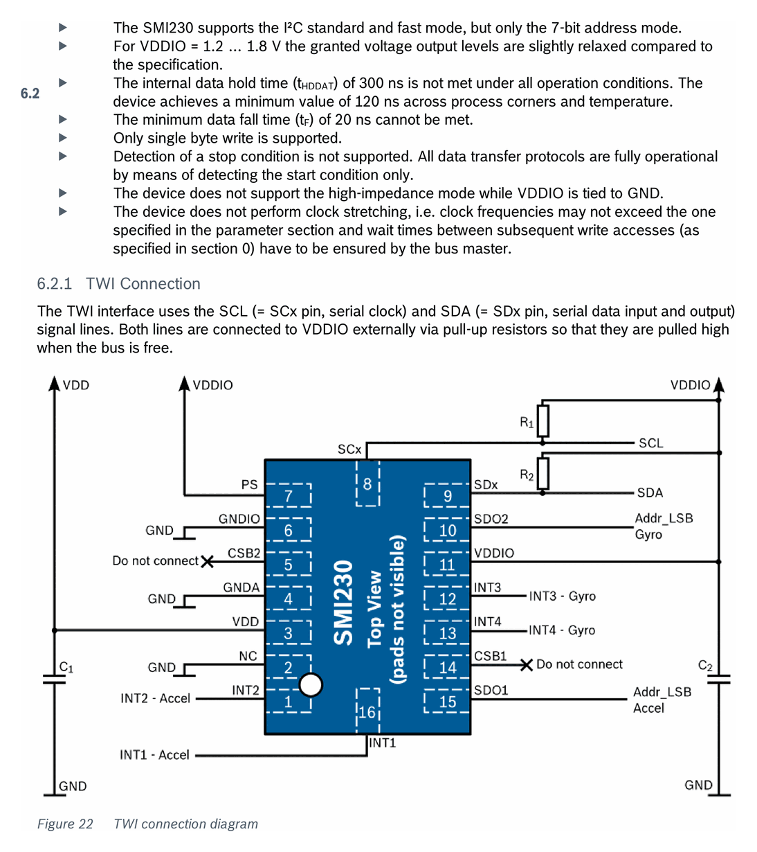
| 7 | PS | Digital In | Protocol select (GND=SPI, VDDIO=TWI) |
| 8 | SCx | Digital In | Serial clock (SCK or SCL) |
| 9 | SDx | Digital I/O | Serial data in (SPI: SDI; TWI: SDA) |
| 10 | SDO2 | Digital Out | SPI serial data out gyroscope; TWI addr select gyro |
| 11 | VDDIO | Supply | Digital I/O supply voltage |
| 12 | INT3 | Digital I/O | Interrupt pin (GYR #1) |
| 13 | INT4 | Digital I/O | Interrupt pin (GYR #2) |
| 14 | CSB1 | Digital In | SPI chip select accelerometer |
| 15 | SDO1 | Digital Out | SPI serial data out accelerometer; TWI addr select accel |
| 16 | INT1 | Digital I/O | Interrupt pin (ACC #1) |
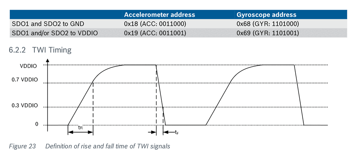
TWI/I2C Addresses:
| Configuration | Accelerometer | Gyroscope |
|---|---|---|
| SDO1/SDO2 to GND | 0x18 | 0x68 |
| SDO1/SDO2 to VDDIO | 0x19 | 0x69 |
Absolute Maximum Ratings
| Parameter | Condition | Min | Max | Unit |
|---|---|---|---|---|
| Voltage at VDD pin | — | -0.3 | 4 | V |
| Voltage at VDDIO pin | — | -0.3 | 4 | V |
| Voltage at any logic pin | — | -0.3 | VDDIO+0.3 | V |
| Passive storage temperature | <=65% RH | -50 | +150 | degC |
| Mechanical shock | duration <=200 us | — | 10000 | g |
| Mechanical shock | duration <=1 ms | — | 2000 | g |
| Free fall onto hard surfaces | — | — | 1.2 | m |
| ESD (HBM) | any pin | — | 2 | kV |
| ESD (CDM) | — | — | 500 | V |
| ESD (MM) | — | — | 200 | V |
Recommended Operating Conditions
| Parameter | Min | Typ | Max | Unit |
|---|---|---|---|---|
| Supply voltage VDD | 2.4 | 3.3 | 3.6 | V |
| Supply voltage VDDIO | 1.62 | 3.3 | 3.6 | V |
| Operating temperature | -40 | — | +105 | degC |
Lifetime conditions are per AEC-Q100 Grade 2 requirements.
Electrical Characteristics
Power Supply
| Parameter | Condition | Min | Typ | Max | Unit |
|---|---|---|---|---|---|
| VDD supply voltage | — | 2.4 | 3.3 | 3.6 | V |
| VDDIO supply voltage | — | 1.62 | 3.3 | 3.6 | V |
| Input low voltage (V_IL) | — | — | — | 0.3 VDDIO | — |
| Input high voltage (V_IH) | SPI | 0.7 VDDIO | — | — | — |
| Output low voltage (V_OL) | I_OL <=2 mA | — | — | 0.23 VDDIO | — |
| Output high voltage (V_OH) | I_OL <=2 mA | 0.8 VDDIO | — | — | — |
No limitations on VDD/VDDIO relative voltage levels as long as each is within operating range. Device can be switched off (VDD=0V) while keeping VDDIO on, or vice versa.
Accelerometer
Default config: +/-2 g range, 47 Hz bandwidth (100 Hz ODR).
| Parameter | Condition | Typ | Unit |
|---|---|---|---|
| Supply current (normal mode) | VDD=VDDIO=3.0V, 25 degC, @1Hz | 170 | uA |
| Supply current (suspend mode) | VDD=VDDIO=3.0V, 25 degC | 3 | uA |
| Measurement range | selectable | +/-2, +/-4, +/-8, +/-16 | g |
| Resolution @ +/-2 g | 25 degC | 16384 | LSB/g |
| Resolution @ +/-4 g | 25 degC | 8192 | LSB/g |
| Resolution @ +/-8 g | 25 degC | 4096 | LSB/g |
| Resolution @ +/-16 g | 25 degC | 2048 | LSB/g |
| Sensitivity tolerance | incl. temp + lifetime | 1 | % |
| Sensitivity temp drift (TCS) | — | +/-0.004 | %/K |
| Zero-g offset | incl. temp + lifetime | 20 | mg |
| Zero-g offset temp drift | over full temp range | +/-0.2 | mg/K |
| Output data rate (ODR) | selectable | 12.5 - 1600 | Hz |
| Bandwidth (3 dB) | depends on ODR/OSR | 5.06 - 684 (max 353 Z-axis) | Hz |
| Nonlinearity | BFSL, no lifetime | 10 | mg |
| Cross axis sensitivity | any two axes | +/-1 | % |
| Alignment error | relative to package | 0.5 | deg |
Gyroscope
Default config: +/-2000 deg/s range, 47 Hz bandwidth.
| Parameter | Condition | Typ | Unit |
|---|---|---|---|
| Supply current (normal mode) | VDD=VDDIO=3.0V, 25 degC | 5 | mA |
| Supply current (suspend mode) | VDD=VDDIO=3.0V, 25 degC | 25 | uA |
| Supply current (deep suspend) | VDD=VDDIO=3.0V, 25 degC | <5 | uA |
| Measurement range | selectable | +/-125, +/-250, +/-500, +/-1000, +/-2000 | deg/s |
| Resolution @ +/-125 deg/s | 25 degC | 16.38 | LSB/(deg/s) |
| Resolution @ +/-250 deg/s | 25 degC | 32.77 | LSB/(deg/s) |
| Resolution @ +/-500 deg/s | 25 degC | 65.54 | LSB/(deg/s) |
| Resolution @ +/-1000 deg/s | 25 degC | 131.07 | LSB/(deg/s) |
| Resolution @ +/-2000 deg/s | 25 degC | 262.14 | LSB/(deg/s) |
| Sensitivity tolerance | incl. temp + lifetime | +/-1 | % |
| Sensitivity temp drift (TCS) | over full temp range | +/-0.03 | %/K |
| Zero-rate offset | lifetime + temp effects | +/-0.5 | deg/s |
| Zero-rate offset temp drift | over full temp range | +/-0.015 | (deg/s)/K |
| Bandwidth | selectable | 12, 23, 32, 47, 64, 116, 230, 523 (unfiltered) | Hz |
| Noise (rms) | 25 degC, nominal VDD | 0.1 | deg/s |
| Cross axis sensitivity | incl. temp + lifetime | +/-2 | % |
Temperature Sensor
| Parameter | Typ | Unit |
|---|---|---|
| Accelerometer temp range | -104 to +150 | degC |
| Accelerometer temp slope | 0.125 | K/LSB |
| Accelerometer temp offset error (25 degC) | +/-1 | K |
| Gyroscope temp slope | 0.5 | K/LSB |
| Gyroscope temp offset (25 degC) | +/-5 | K |
| Resolution | 11-bit | — |
Power Consumption
Power Modes — Accelerometer
| Mode | Description | Current |
|---|---|---|
| Normal | Full operation, configurable ODR | 170 uA typ |
| Suspend | Low power, no measurements | 3 uA typ |
Power Modes — Gyroscope
| Mode | Description | Current |
|---|---|---|
| Normal | Full operation | 5 mA typ |
| Suspend | Drive system off, fast wake-up | 25 uA typ |
| Deep suspend | Minimum power, slow wake-up | <5 uA typ |
Communication Interface
SPI Interface
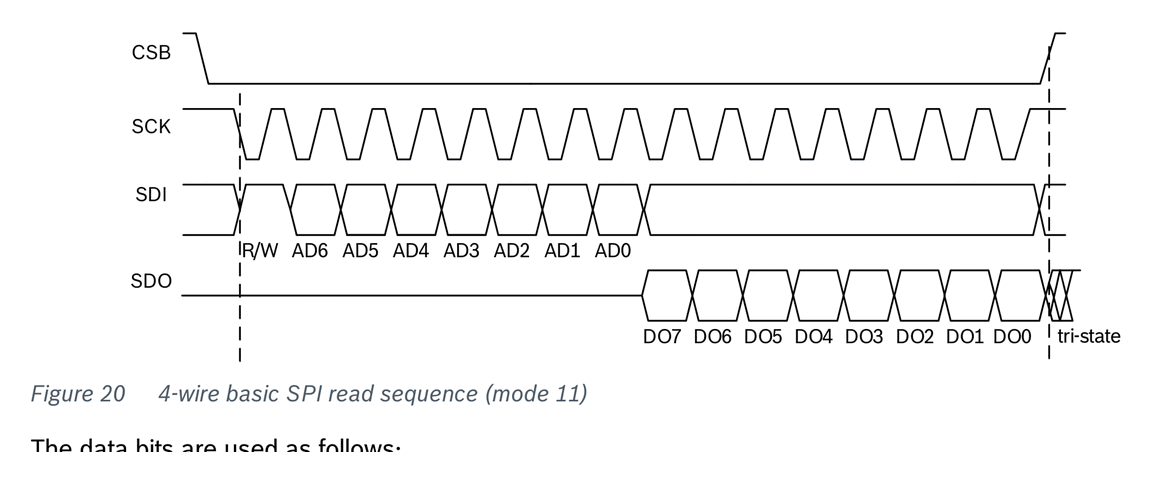
4-wire SPI with separate chip selects for accelerometer (CSB1, pin 14) and gyroscope (CSB2, pin 5). Compatible with SPI modes 00 and 11 (auto-selected based on SCK state at CSB falling edge).
| Parameter | Min | Max | Unit |
|---|---|---|---|
| Clock frequency (f_SCK) | — | 10 | MHz |
| SCK low/high pulse | 20 | — | ns |
| SDI setup time | 20 | — | ns |
| SDI hold time | 20 | — | ns |
| SDO output delay (25 pF, VDDIO=2.4V) | — | 40 | ns |
| CSB setup time | 20 | — | ns |
| CSB hold time | 40 | — | ns |
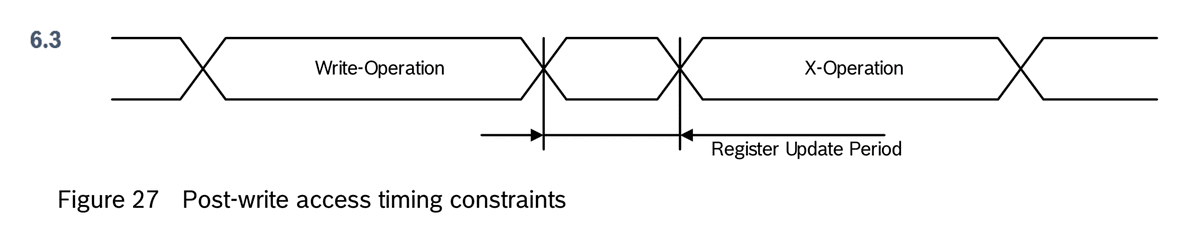
| Idle time between write accesses | 2 | — | us |
Important: When reading the accelerometer via SPI, a dummy byte is sent first. A single byte read requires reading 2 bytes in burst mode (discard the first byte). For burst reads (e.g., 6 bytes of accel data from 0x12), read 7 bytes and discard the first.
TWI/I2C Interface
Compatible with I2C standard and fast mode (7-bit address only). Supports burst read with auto-incrementing address. Internal watchdog timer prevents bus lockup.
| Parameter | Min | Max | Unit |
|---|---|---|---|
| Clock frequency (f_SCL) | 0 | 400 | kHz |
| SCL low period | 1.3 | — | us |
| SCL high period | 0.6 | — | us |
| SDA setup time | 0.1 | — | us |
| Start/repeated start setup/hold | 0.6 | — | us |
| Stop setup time | 0.6 | — | us |
| Bus free time (t_BUF) | 1.3 | — | us |
| Idle between write accesses | 2 | — | us |
| Rise time | 20 | 300 | ns |
| Fall time | 0 | 300 | ns |
Limitations: Only single byte write supported. No clock stretching. Minimum data hold time of 120 ns (spec is 300 ns). Only 7-bit address mode.
Software API
Device Initialization
After power-on, the device performs a power-on reset (POR) which resets all registers to defaults. Application-specific settings must be reconfigured after POR. The accelerometer interface type (SPI/TWI) is determined by the CSB1 pin state during POR. The gyroscope interface type is determined by the PS pin.
Accelerometer Register Map (Key Registers)
| Address | Name | Description |
|---|---|---|
| 0x00 | ACC_CHIP_ID | Chip identification (0x1F) |
| 0x02 | ACC_ERR_REG | Error register |
| 0x03 | ACC_STATUS | Data ready status |
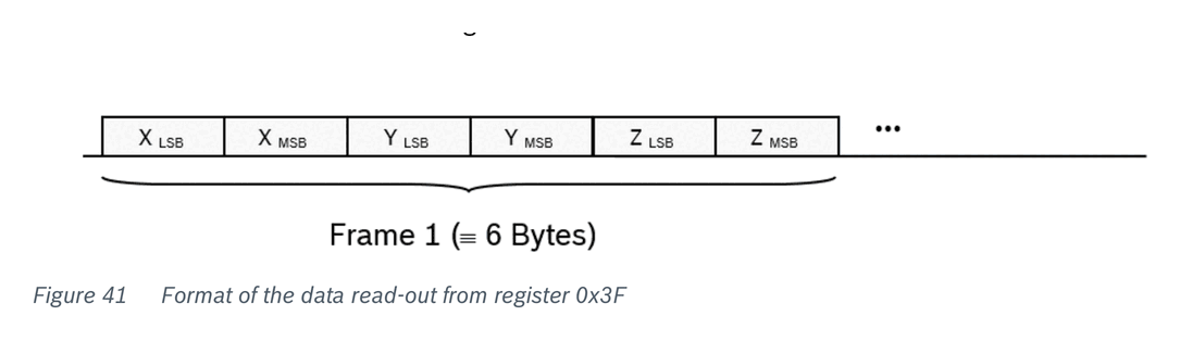
| 0x12-0x17 | ACC_X/Y/Z | Acceleration data (LSB/MSB per axis) |
| 0x18-0x1A | SENSORTIME | 24-bit sensor time |
| 0x1C | INT_STATUS_0 | Interrupt status |
| 0x22-0x23 | TEMP | Temperature data (MSB/LSB) |
| 0x24-0x25 | FIFO_LENGTH | FIFO byte count |
| 0x26 | FIFO_DATA | FIFO data readout |
| 0x40 | ACC_CONF | ODR, bandwidth, power mode config |
| 0x41 | ACC_RANGE | Measurement range selection |
| 0x45-0x4A | FIFO config | FIFO mode and watermark |
| 0x53 | INT1_IO_CONF | INT1 pin configuration |
| 0x54 | INT2_IO_CONF | INT2 pin configuration |
| 0x58 | INT_MAP_DATA | Data ready interrupt mapping |
| 0x59-0x5A | FEATURE config | Feature interrupt engine |
| 0x5B-0x5E | INIT config | Config file loading |
| 0x7C | ACC_SELF_TEST | Self-test trigger |
| 0x7E | ACC_SOFTRESET | Soft reset (write 0xB6) |
Gyroscope Register Map (Key Registers)
| Address | Name | Description |
|---|---|---|
| 0x00 | GYRO_CHIP_ID | Chip identification (0x0F) |
| 0x02-0x07 | RATE_X/Y/Z | Angular rate data (LSB/MSB per axis) |
| 0x08 | GYRO_INT_STAT_1 | Interrupt status |
| 0x0F | GYRO_RANGE | Measurement range selection |
| 0x10 | GYRO_BANDWIDTH | Filter bandwidth selection |
| 0x11 | GYRO_LPM1 | Power mode control |
| 0x14 | GYRO_SOFTRESET | Soft reset (write 0xB6) |
| 0x15 | GYRO_INT_CTRL | Interrupt enable |
| 0x16 | INT3_INT4_IO_CONF | Interrupt pin configuration |
| 0x18 | INT3_INT4_IO_MAP | Interrupt mapping |
| 0x1E | GYRO_SELF_TEST | Self-test trigger |
| 0x3C-0x3E | FIFO config | FIFO control |
Data Synchronization
The accelerometer and gyroscope can be synchronized so that acceleration and angular rate data correspond to the same timestamp. This requires uploading a configuration file to the accelerometer's feature engine. When enabled, synchronized data is available through dedicated registers (INT_SYNC_X/Y/Z at 0x1E-0x28).
Interrupt Features
Configurable via config file upload to the accelerometer feature engine:
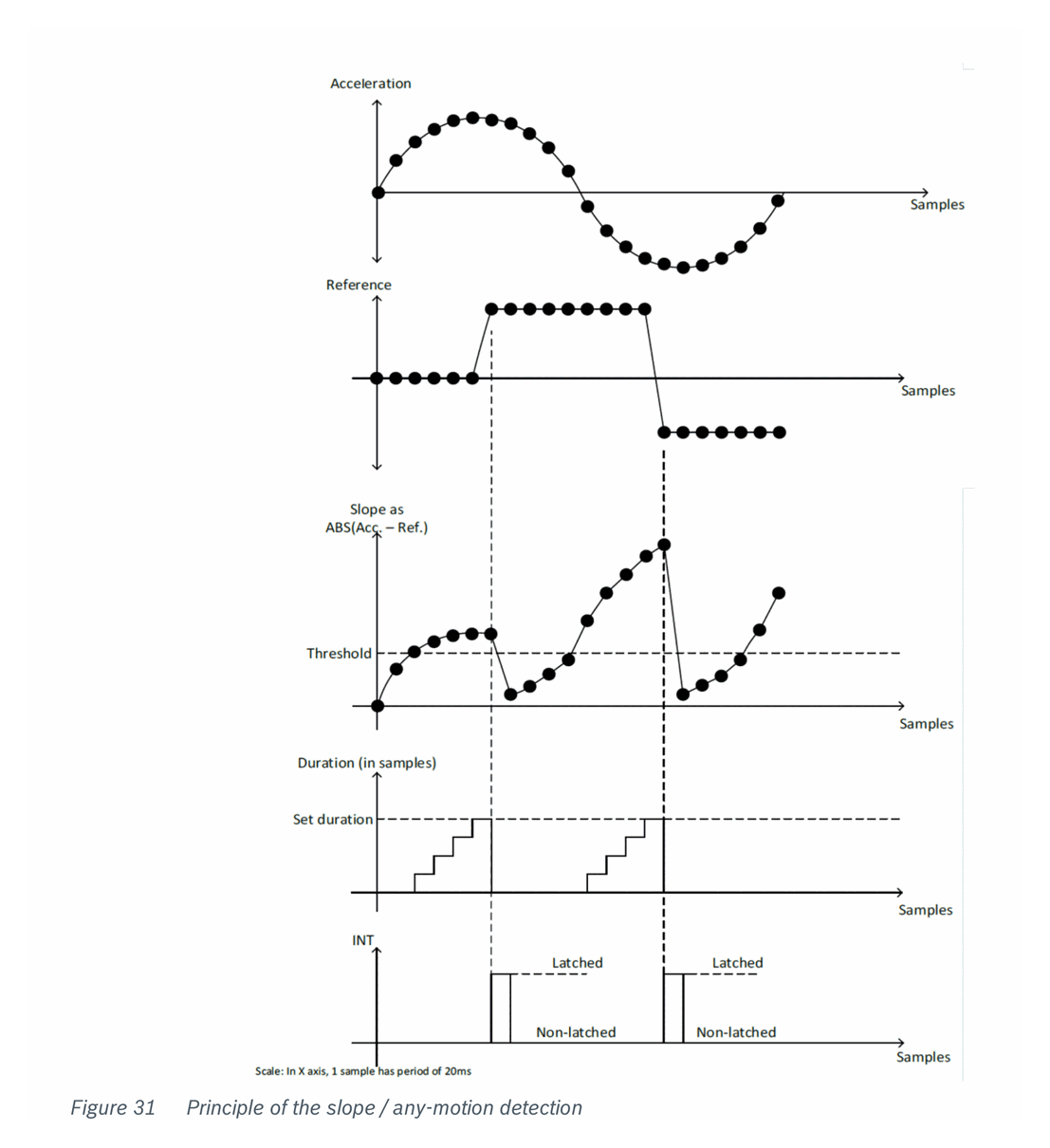
- Any-motion / Slope detection — detects sudden acceleration changes
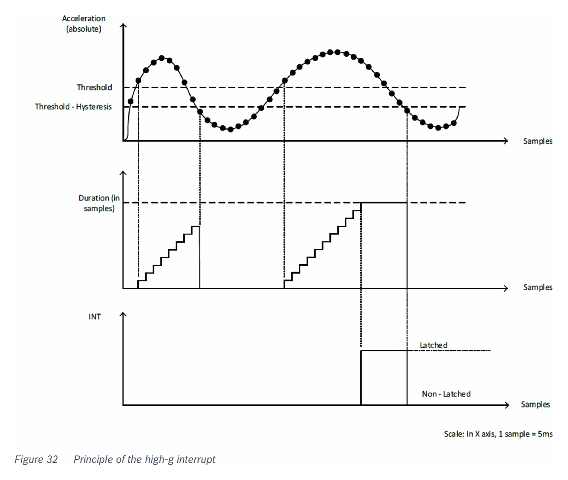
- High-g detection — detects acceleration exceeding a programmable threshold
- Low-g detection — detects free-fall or low-gravity conditions
- Orientation detection — detects device orientation relative to gravity (portrait/landscape, face-up/face-down)
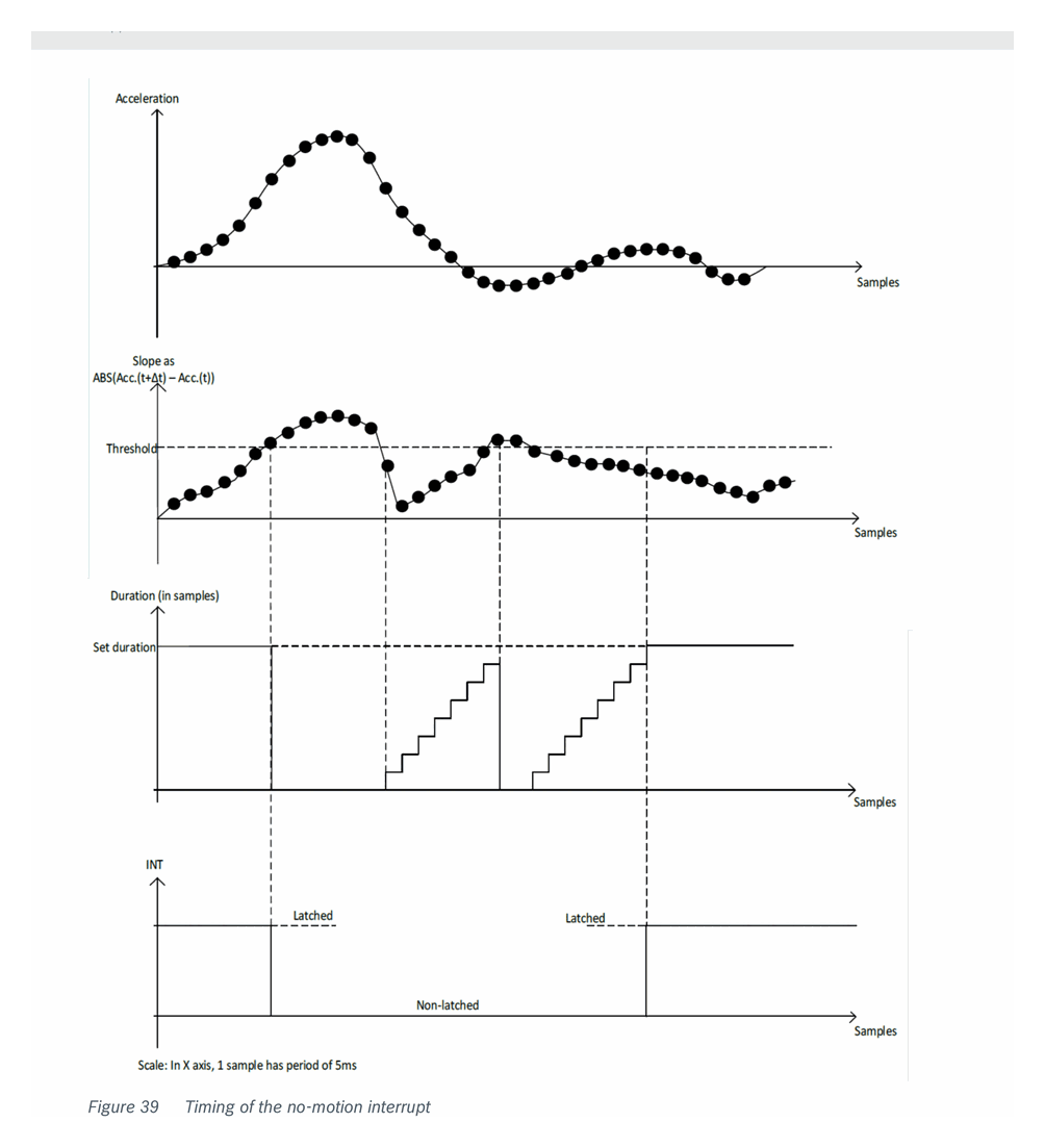
- No-motion detection — detects when device is stationary
FIFO Operation
Both accelerometer and gyroscope have independent on-chip FIFO buffers:
- Accelerometer FIFO: up to 1024 bytes, supports FIFO, stream, and stream-to-FIFO modes
- Gyroscope FIFO: up to 100 frames, supports FIFO and stream modes
- Configurable watermark interrupts and overrun detection
Self-Test
- Accelerometer: Apply electrostatic self-test force, verify output difference is within specified range
- Gyroscope: Triggered by writing to GYRO_SELF_TEST register, bit 0 of result indicates pass/fail
Thermal Information
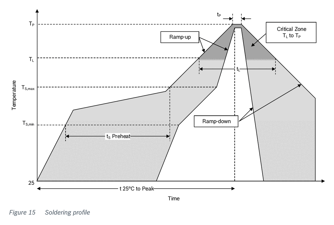
Reflow Soldering Profile (Pb-Free)
| Parameter | Value |
|---|---|
| Preheat temperature | 150 - 200 degC |
| Preheat time | 60 - 180 s |
| Liquidus temperature (T_L) | 217 degC |
| Time above T_L | 60 - 150 s |
| Peak temperature (T_P) | 260 degC max |
| Time within 5 degC of peak | 20 - 40 s |
| Ramp-up rate (max) | 3 degC/s |
| Ramp-down rate (max) | 6 degC/s |
| Time 25 degC to peak | 8 min max |
| Maximum reflow cycles | 3 |
MSL rating: JEDEC Level 1
Packages
| Parameter | Value | Unit |
|---|---|---|
| Package type | LGA | — |
| Pin count | 16 | — |
| Width | 3.00 | mm |
| Length | 4.50 | mm |
| Height | 0.95 | mm |
| Weight | 27.48 | mg |
| Pad pitch | 0.625 | mm |
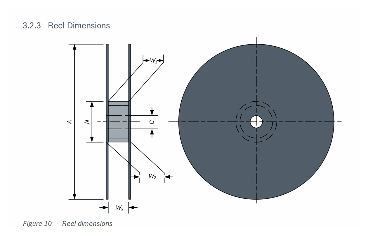
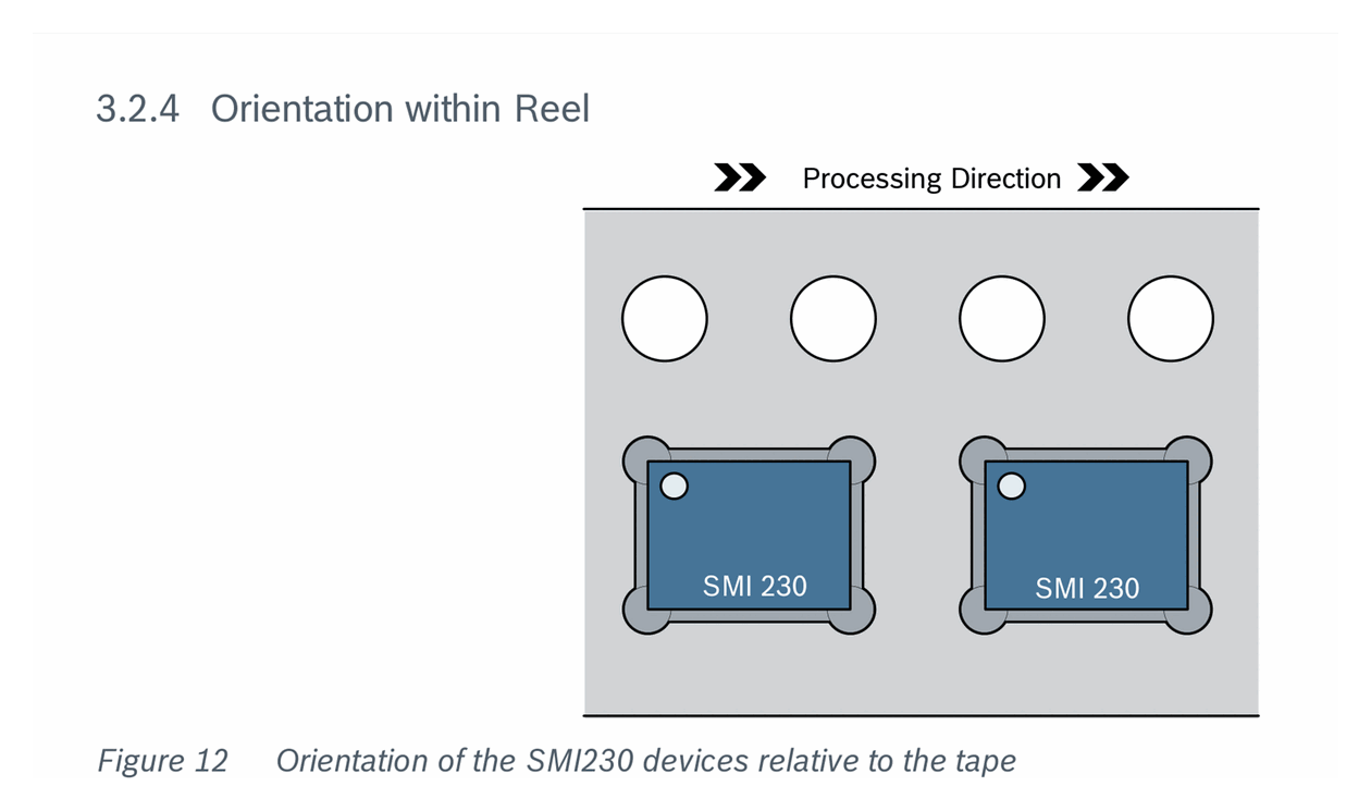
| Reel quantity | 5000 | pcs |
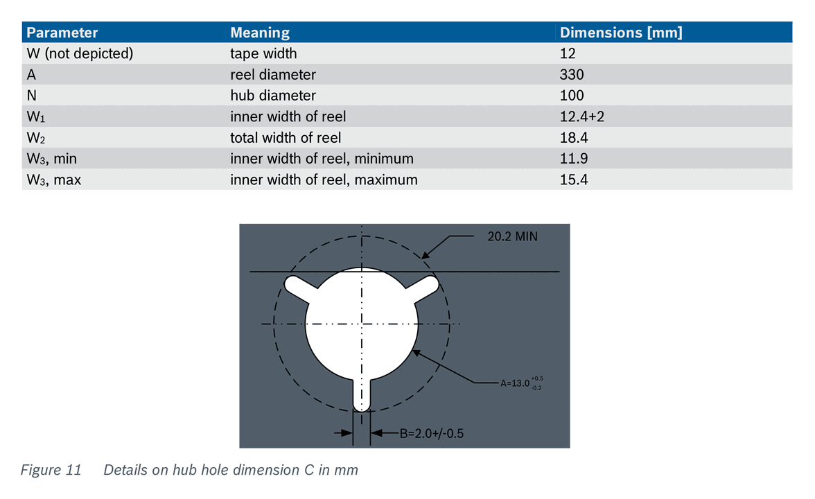
| Reel diameter | 330 | mm |
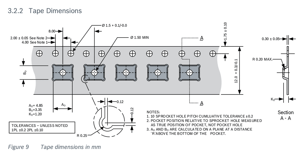
| Tape width | 12 | mm |
Tolerances: +/-0.05 mm unless otherwise specified. Compliant with RoHS (2002/95/EC), WEEE (2012/19/EU), and halogen-free.
Applications
- High-end dead reckoning navigation
- eCall systems
- Telematics and electronic tolling
- Vehicle dynamics data logging
- Car alarm / anti-theft
- ADAS sensor fusion