COSMIIC Remote Module Network Interface
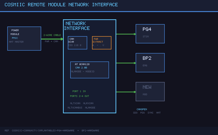
UnreviewedTJA1050T CAN transceiver + MIC5205 5V LDO on a 32×24mm Adom molecule — bridges the AT90CAN128 to the 2-conductor COSMIIC implant network with 4-port CANopen fanout (1 upstream in + 3 downstream out)
3D Model
Symbol & Footprint
Schematic

PCB Footprint

COSMIIC Remote Module Network Interface
The Remote Module Network Interface is the shared circuit block present on every COSMIIC remote module (PG4, BP2, and derivatives). It bridges the AT90CAN128's built-in CAN controller to the implanted 2-conductor network, extracts regulated 5V from the network supply, and fans out to 4 ports (1 upstream in + 3 downstream out) for branching tree topology.
How it works
Every remote module connects to the COSMIIC implanted network through a single 2-conductor cable. That cable carries both the CANopen differential bus and the DC supply voltage on the same conductors (NET_P = CANH / supply+, NET_N = CANL / supply return). The network interface circuit:
- Extracts regulated 5V — NET_P (4.7–9.6 V from the PM) feeds the U2 LDO; regulated 5V powers the AT90CAN128 and the CAN transceiver
- Transceives CAN — U1 (TJA1050T) bridges the AT90CAN128's digital CANTX/CANRX pins to the physical CANH/CANL bus
- Fans out to 4 ports — J1–J4 connectors branch the same CAN bus to 1 upstream input + 3 downstream outputs
- Hardware node addressing — MC_ANODE exposes the hardware node address line to the AT90CAN128
U1's Rs pin is pulled low through R1 (10 kΩ) for slope-controlled mode, which limits dV/dt on the bus edges and reduces EMI — important for implantable devices.
Hardware
| Parameter | Value |
|---|---|
| CAN Controller | AT90CAN128 built-in (ISO 11898, CAN 2.0B) |
| CAN Transceiver | NXP TJA1050T (SOIC-8, 1 Mbps, 5V) |
| LDO Regulator | MIC5205-5.0YM5 (SOT-23-5, 5V, 150 mA) |
| Network Cable | 2-conductor (CAN differential + power superimposed) |
| Network Ports | 4 total — J1 upstream in, J2–J4 downstream out |
| Topology | Branching tree (up to 24 nodes from a single PM) |
| Network Voltage | 4.7–9.6 V (adjustable from PM) |
| Output Voltage | 5 V regulated |
| Protocol | CANopen |
| Node Addressing | Hardware-configured (MC_ANODE) |
| PCB Size | 32 × 24 mm Adom molecule |
Components
| Ref | Part | Value | Package | JLCPCB |
|---|---|---|---|---|
| U1 | NXP TJA1050T | CAN transceiver, 1 Mbps | SOIC-8 | C6952 |
| U2 | MIC5205-5.0YM5 | 5V LDO, 150 mA, 16V max in | SOT-23-5 | C89758 |
| J1–J4 | 2-pin header | COSMIIC network port | 2.54mm pitch | — |
| C1 | 100nF | TJA1050T VCC decoupling | 0402 | C1525 |
| C2 | 10µF | LDO input cap | 0805 | — |
| C3 | 22µF | LDO output cap (stability) | 0805 | — |
| C4 | 100nF | TJA1050T VREF bypass | 0402 | C1525 |
| R1 | 10 kΩ | TJA1050T slope control (Rs) | 0402 | C25744 |
Production note: For the full 4.7–9.6 V network range, replace U2 with LM1117S-5.0 (C126028, SOT-223-3, 800 mA) which handles up to 15 V input.
Signal Net Names
| Net | Description |
|---|---|
NLTXCAN / MC_CANTX |
CAN TX from AT90CAN128 to U1.TXD |
NLRXCAN / MC_CANRX |
CAN RX from U1.RXD to AT90CAN128 |
NLTXCANBUS / CANH |
CAN bus positive on network cable |
NLTXCANBUS / CANL |
CAN bus negative on network cable |
NLANODE / MC_ANODE |
Hardware node address input |
Machine Contacts
| Contact | Side | Function |
|---|---|---|
| MC_CANTX | Left | CAN TX from AT90CAN128 → U1.TXD |
| MC_CANRX | Left | CAN RX from U1.RXD → AT90CAN128 |
| MC_VCC5V | Left | 5V regulated output to module |
| MC_GND | Left | Ground reference |
| MC_VIN | Right | Network supply input (4.7–9.6V) |
| MC_CANH | Right | CAN bus positive |
| MC_CANL | Right | CAN bus negative |
| MC_ANODE | Right | CANopen node address |
Architecture
        Network Cable (2-wire: NET_P/CANH and NET_N/CANL)
                │
    ┌───────────▼─────────────┐
    │   J1 — Port 1 (in)      │
    └───────────┬─────────────┘
                │
    ┌───────────▼──────────────────────────────────┐
    │        Network Interface (32×24mm)           │
    │                                              │
    │  ┌──────────────┐   ┌────────────────────┐  │
    │  │ U2 MIC5205   │   │ U1 TJA1050T        │  │
    │  │ 5V LDO       │   │ CAN Transceiver    │  │
    │  │ NET_P → 5V   │   │ CANTX/CANRX (MCU)  │  │
    │  └──────┬───────┘   │ CANH/CANL (bus)    │  │
    │         │ VCC       └──────┬──────────────┘  │
    │         └──────────────────┤                 │
    │                            │ CANH / CANL     │
    └────────────────────────────┼─────────────────┘
                │          │          │
    ┌───────────▼─┐ ┌───────▼──┐ ┌───▼────────┐
    │ J2 (out 1)  │ │J3 (out 2)│ │J4 (out 3)  │
    └─────────────┘ └──────────┘ └────────────┘
CANopen Protocol
The PM acts as NMT master; remote modules are NMT slaves.
| Message Type | Direction | Purpose |
|---|---|---|
| NMT | PM → Module | State machine transitions (Operational, Pre-op, Reset) |
| SYNC | PM → All | Cyclic timing reference (controls stimulation frequency, data windows) |
| SDO | Bidirectional | Point-to-point Object Dictionary read/write (configuration, testing) |
| PDO | Module → PM | High-speed broadcast of sensor data / stimulation status |
| Emergency | Module → PM | Fault reporting |
Build
EDA: tscircuit (TSX) — source bundle included in Files below.
LDO note: Production modules use LM1117S-5.0 (C126028, SOT-223) which handles the full 4.7–9.6V network range. The SOT-23-5 MIC5205 in this reference design targets bench testing where network voltage is kept ≤6V.
Firmware: COSMIIC-Community/Implantables-PG4-App / Implantables-BP2-App — C, AVR toolchain
Source
All design files are open source under CERN-OHL-P-2.0 (hardware) and MIT (firmware).
Files
| File | Description |
|---|---|
cosmiic-network-interface-source.tar.gz |
tscircuit project source (lib/index.tsx, package.json, config) |
schematic.svg |
Circuit schematic (all connections) |
pcb.svg |
PCB layout (32×24mm, component placement) |
3d.glb |
3D board model |
Reference Implementation
The equivalent analog circuit appears as a dedicated schematic sheet in every remote module Altium project:
- PG4 — page 4 of 8 ("CAN Interface") in COSMIIC-Community/Implantables-PG4-Hardware
- BP2 — page 4 of 6 ("Network Interface") in COSMIIC-Community/Implantables-BP2-Hardware
NSF Relevance
The standardized remote module network interface enables multi-node implantable research systems with a single power and communication cable per branch. Researchers can add sensing or stimulation nodes to a running implant without architectural changes, enabling adaptive closed-loop protocols with real-time bidirectional data flow.
Science Drivers
implantable_healthcare
Created by: noah
Version: v1
Category: other