BMP581
UnreviewedBosch Sensortec BMP581 — Next-gen barometric pressure sensor with ultra-low noise and power
Source: Bosch Sensortec Datasheet (BST-BMP581-DS004-13)
Manufacturer: Bosch Sensortec
Part Number: BMP581
Document: BST-BMP581-DS004-13 — Rev 1.13, April 2025
Description
The BMP581 is a next-generation absolute barometric pressure sensor from Bosch Sensortec. Its small dimensions (2.0 x 2.0 x 0.75 mm), ultra-low noise (<0.1 Pa RMS natively), and extremely low power consumption (1.3 uA at 1 Hz) make it ideal for mobile, wearable, and IoT applications. The sensor provides true absolute pressure and temperature outputs with on-chip linearization and temperature compensation.
The BMP581 features a 32-sample on-chip FIFO buffer, programmable interrupts including pressure-change detection, configurable IIR low-pass filtering, and 6 bytes of user-programmable NVM. It supports I2C (Fm+), I3C (12.5 MHz), and SPI (12 MHz) interfaces with independent VDD and VDDIO power domains.
Key Specifications
| Parameter | Value |
|---|---|
| Supply Voltage (VDD) | 1.71V to 3.6V |
| Interface Voltage (VDDIO) | 1.08V to 3.6V |
| Digital Interface | I2C (1 MHz Fm+), I3C (12.5 MHz), SPI (12 MHz) |
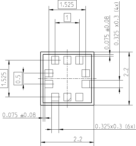
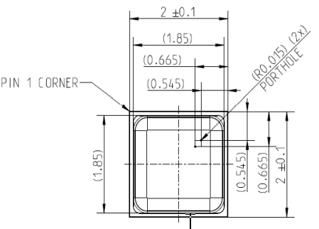
| Package | 2.0 x 2.0 x 0.75 mm LGA-10 |
| Pressure Range | 30 to 125 kPa (300 to 1250 hPa) |
| Temperature Range | -40 to +85 C |
| Pressure Noise (RMS) | <0.1 Pa (high res), 0.78 Pa (low power) |
| Absolute Pressure Accuracy | +/-0.5 hPa |
| Deep Standby Current | 0.55 uA |
| Low Power Mode Current | 1.3 uA at 1 Hz |
| Pin Count | 10 |
Features
- Ultra-low noise: <0.1 Pa RMS natively without low-pass filter
- Ultra-low current: 0.55 uA deep standby, 1.3 uA at 1 Hz low power mode
- On-chip FIFO buffer for up to 32 pressure/temperature samples
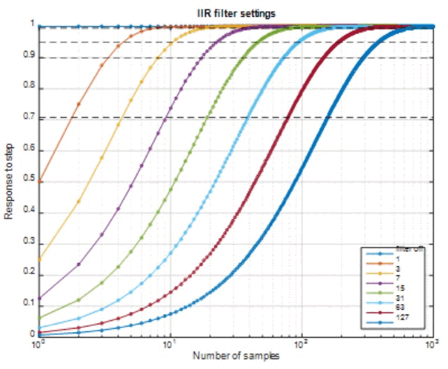
- Programmable IIR low-pass filter with configurable bandwidth
- Output data rates up to 480 Hz (continuous mode), 0.125 to 240 Hz (normal mode)
- Programmable interrupts: data ready, FIFO watermark/full, pressure-change detection (out-of-range)
- 6 bytes user-programmable non-volatile memory (NVM)
- Independent VDD and VDDIO power domains (can be energized in any order)
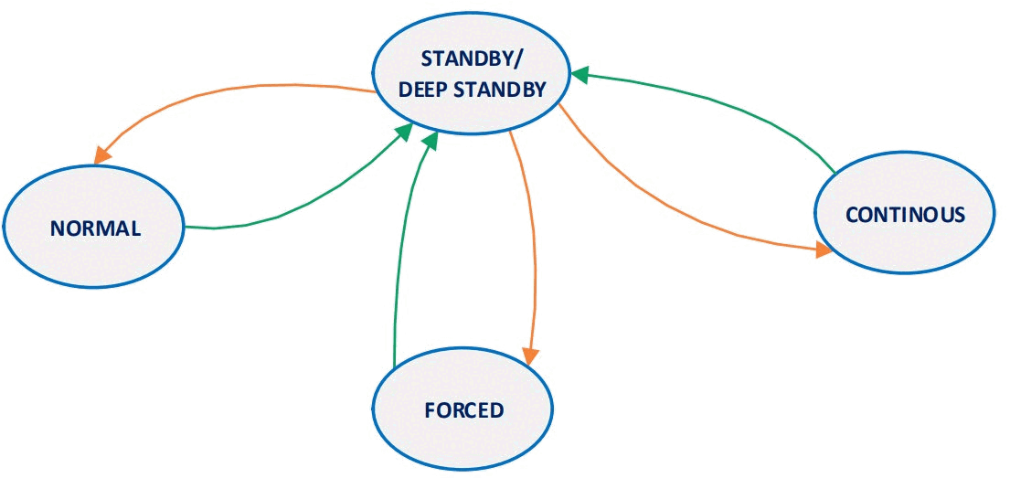
- Multiple power modes: Deep Standby, Standby, Forced, Normal, Low Power Normal, Continuous
- Configurable oversampling (1x to 128x) for pressure and temperature
- True absolute pressure and temperature with on-chip linearization
- I3C support with in-band interrupts
- RoHS compliant, halogen-free, lead-free, MSL1
Pin Configuration
| Pin | Name | Type | Description |
|---|---|---|---|
| 1 | VDDIO | Power | Digital interface supply (1.08V to 3.6V) |
| 2 | SCK | Input | Serial clock input |
| 3 | VSS | Power | Ground |
| 4 | SDI | In/Out | Serial data input (SPI MOSI / I2C SDA) |
| 5 | SDO | In/Out | Serial data output (SPI MISO / I2C addr select) |
| 6 | CSB | Input | Chip select (active low); connect to VDDIO for I2C/I3C |
| 7 | INT | Output | Interrupt output (configurable push-pull/open-drain) |
| 8 | VSS | Power | Ground |
| 9 | VSS | Power | Ground |
| 10 | VDD | Power | Analog supply (1.71V to 3.6V) |
Absolute Maximum Ratings
| Parameter | Min | Max | Unit |
|---|---|---|---|
| Supply Voltage VDD | -0.3 | 4.3 | V |
| Supply Voltage VDDIO | -0.3 | 4.3 | V |
| Voltage at any I/O pin | VSSIO - 0.3 | VDDIO + 0.3 | V |
| Storage Temperature | -40 | +125 | C |
Electrical Characteristics
| Parameter | Conditions | Min | Typ | Max | Unit |
|---|---|---|---|---|---|
| Supply Voltage VDD | - | 1.71 | 1.8/3.3 | 3.6 | V |
| Supply Voltage VDDIO | - | 1.08 | 1.2/1.8/3.3 | 3.6 | V |
| Deep Standby Current | 25 C, VDD=VDDIO=1.8V | - | 0.55 | - | uA |
| Deep Standby Current | 25 C, VDD=VDDIO=3.6V | - | 0.55 | - | uA |
| Standby Current | 25 C, VDD=VDDIO=1.8V | - | 1.0 | - | uA |
| Low Power Mode Current | OSR lowest, 1 Hz, 25 C | - | 1.3 | - | uA |
| High Resolution Current | OSR high res, 30 Hz, 25 C | - | 75 | 80 | uA |
| Peak Current | Maximum DC | - | 260 | - | uA |
| Power-up Time | VDD/VDDIO above min | - | 2 | - | ms |
| I2C Clock | - | - | - | 1 | MHz |
| I3C Clock | - | - | - | 12.5 | MHz |
| SPI Clock | - | - | - | 12 | MHz |
| Pressure Noise (low power) | OSR lowest power | - | 0.78 | 0.95 | Pa RMS |
| Pressure Noise (high res) | OSR high resolution | - | 0.08 | - | Pa RMS |
| Absolute Pressure Accuracy | 300-1100 hPa, -5 to 65 C | - | - | +/-30 | Pa |
| Relative Pressure Accuracy | 700-1100 hPa, 15-55 C | - | - | +/-6 | Pa |
| Temperature Accuracy | -5 to 55 C | - | - | +/-0.5 | K |
| Offset Temp Coefficient | - | - | +/-0.5 | - | Pa/K |
Power Consumption
| Parameter | Conditions | Typ | Unit |
|---|---|---|---|
| Deep Standby | 25 C, 1.8V | 0.55 | uA |
| Standby | 25 C, 1.8V | 1.0 | uA |
| Low Power Mode | OSR lowest, 1 Hz | 1.3 | uA |
| High Resolution Mode | OSR high res, 30 Hz | 75 | uA |
| Peak Current | Maximum DC | 260 | uA |
Communication Interface
The BMP581 supports three digital interfaces: I2C (Fast Mode Plus up to 1 MHz), I3C (up to 12.5 MHz), and SPI (3-wire and 4-wire, up to 12 MHz).
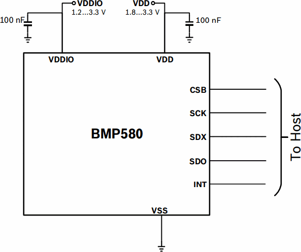
I2C: The 7-bit device address is 1000110 (0x46) when SDO is connected to GND, or 1000111 (0x47) when SDO is connected to VDDIO. CSB must be connected to VDDIO for I2C mode. External pull-up resistors required on SDA and SCL. Use 100 nF bypass capacitors on VDD and VDDIO.
I3C: Supports I3C SDR mode with in-band interrupts. CSB must be connected to VDDIO. Provisional ID includes MIPI member ID, Bosch group ID, and device ID.
SPI: Compatible with SPI mode 0 and mode 3. CSB is active low. In SPI 3-wire mode, SDI serves as bidirectional data line; SDO must be left floating.
Packages
| Package | Pins | Body Size | Height |
|---|---|---|---|
| Metal Lid LGA | 10 | 2.0 x 2.0 mm | 0.75 mm |
Software API
A C Sensor API is available for the BMP581, providing higher-level functions for power mode switching, measurement configuration, FIFO management, NVM access, and register read/write operations. The API is fully compatible with the COINES library.
Sensor API: Available at bosch-sensortec.com
Power Modes:
| Mode | Description |
|---|---|
| Deep Standby | Lowest power; limited register access |
| Standby | No measurements; all registers accessible |
| Forced | Single measurement, then returns to Standby |
| Normal | Periodic measurements at configurable ODR (0.125-240 Hz) |
| Low Power Normal | Normal mode with reduced power |
| Continuous | Highest ODR up to 480 Hz |
Oversampling Settings:
| OSR | Pressure Conversion | Temperature Conversion |
|---|---|---|
| 1x | 1.0 ms | 1.0 ms |
| 2x | 1.7 ms | 1.1 ms |
| 4x | 2.9 ms | 1.5 ms |
| 8x | 5.4 ms | 2.1 ms |
| 16x | 10.4 ms | 3.3 ms |
| 32x | 20.4 ms | 5.8 ms |
| 64x | 40.4 ms | 10.8 ms |
| 128x | 80.4 ms | 20.8 ms |
Applications
- Enhancement of GPS navigation (time-to-first-fix, dead-reckoning, slope detection)
- Indoor navigation (floor detection, elevator detection)
- Outdoor navigation and altitude tracking
- Sports applications (calorie counting, activity identification)
- Emergency caller location
- Weather forecast and barometric monitoring
- Vertical velocity indication (rise/sink speed)
- Altitude control of drones and flying toys
- Smart watches and wearable devices
- Virtual and augmented reality applications
Key Formulas
Pressure Output
pressure_Pa = PRESS_DATA[23:0] / 64
Temperature Output
temperature_C = TEMP_DATA[23:0] / 65536
IIR Filter
data_filtered[n] = (data_filtered[n-1] * (coeff - 1) + data_raw[n]) / coeff
Coefficients: 1 (bypass), 2, 4, 8, 16, 32, 64, 128
FIFO Watermark
FIFO can store up to 32 frames
Each PT-frame = 6 bytes (3 pressure + 3 temperature)
Watermark interrupt fires when frame count >= threshold