BMP390 — Digital Barometric Pressure Sensor
UnreviewedBosch Sensortec BMP390. High-performance barometric pressure sensor, 300-1250 hPa, +/-3 Pa relative accuracy, 3.2 uA at 1 Hz, I2C/SPI, 2x2mm LGA-10. Standardized datasheet with 15 extracted diagrams.
Source: Bosch Sensortec Datasheet (BST-BMP390-DS002-07)
Manufacturer: Bosch Sensortec
Part Number: BMP390
Document: BST-BMP390-DS002-07 — Rev 1.7, March 2021
Description
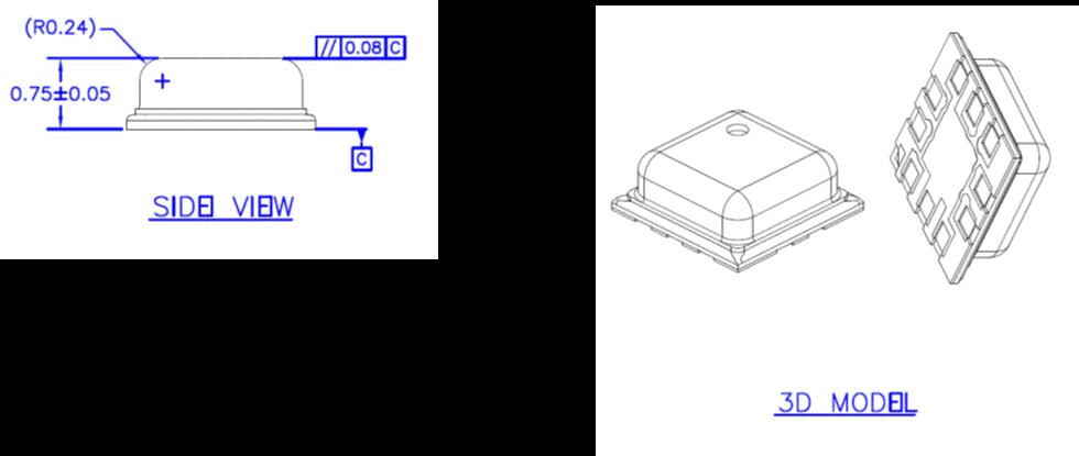
The BMP390 is a high-performance digital barometric pressure sensor from Bosch Sensortec with both pressure and temperature measurement based on proven piezo-resistive sensing principles. The sensor module is housed in an extremely compact 10-pin metal-lid LGA package with a footprint of only 2.0 x 2.0 mm and a maximum height of 0.75 mm. Its small dimensions and low power consumption of 3.2 uA at 1 Hz make it ideal for battery-driven devices such as mobile phones, GPS modules, drones, and wearables.
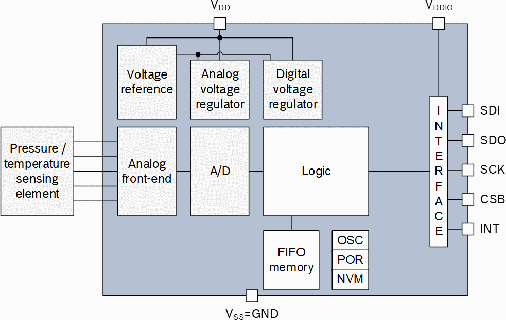
The BMP390 consists of a piezo-resistive pressure sensing element and a mixed-signal ASIC that performs A/D conversions and provides compensation data through a digital interface (I2C or SPI). It offers best-in-class temperature coefficient of offset (TCO) between -20 to 65 degrees C for accurate altitude measurement over a wide temperature range. The sensor is more accurate than its predecessor BMP380, covering a measurement range from 300 hPa to 1250 hPa.
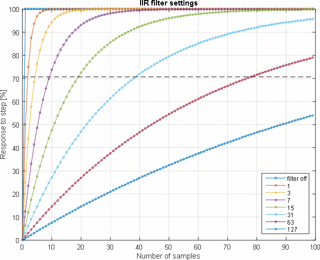
The BMP390 includes a 512-byte FIFO buffer, configurable IIR filter for suppressing short-term pressure disturbances, flexible oversampling settings from ultra-low power to highest resolution, and interrupt functionality including data-ready, FIFO watermark, and FIFO full interrupts. It supports hardware synchronization with external sensors such as Bosch IMUs (e.g., BMI260) for sensor data fusion applications.
Key Specifications
| Parameter | Value |
|---|---|
| Supply Voltage (VDD) | 1.65V to 3.6V |
| Interface Voltage (VDDIO) | 1.2V to 3.6V |
| Operating Temperature | -40 to +85 deg C |
| Operating Pressure Range | 300 to 1250 hPa |
| Relative Accuracy | +/-3 Pa (+/-25 cm) |
| Absolute Accuracy | +/-50 Pa (typ.) |
| Pressure Resolution | 0.016 Pa (highest mode) |
| RMS Noise (lowest) | 0.02 Pa |
| Temperature Accuracy | +/-0.5 deg C at 25 deg C |
| Current (1 Hz, P+T) | 3.2 uA |
| Sleep Current | 1.4 uA (typ.) |
| Max Sampling Rate | 200 Hz |
| Digital Interface | I2C (up to 3.4 MHz), SPI (up to 10 MHz) |
| FIFO Size | 512 bytes |
| Package | 2.0 x 2.0 x 0.75 mm LGA-10 |
| Pin Count | 10 |
Features
- Pressure range 300 to 1250 hPa with relative accuracy of +/-3 Pa (+/-25 cm)
- Best-in-class TCO of +/-0.6 Pa/K for accurate altitude tracking over -20 to 65 deg C
- Ultra-low power consumption: 3.2 uA at 1 Hz, 1.4 uA sleep mode
- Configurable oversampling from 1x (ultra-low power) to 32x (highest resolution, 21-bit)
- Built-in IIR filter with coefficients 0 (off) to 127 for suppressing short-term disturbances
- 512-byte FIFO buffer with watermark, full, and data-ready interrupts
- Dual digital interface: I2C up to 3.4 MHz and SPI (3-wire/4-wire) up to 10 MHz
- Three power modes: sleep, forced (single-shot), and normal (continuous cycling)
- Hardware data synchronization with external sensors (e.g., BMI260 IMU)
- 24-bit pressure and temperature output data
- Separate VDD and VDDIO power domains for flexible level shifting
- RoHS compliant, halogen-free, MSL1
- Compact 2.0 x 2.0 x 0.75 mm metal-lid LGA package
- Chip ID register at 0x60 for device identification
Pin Configuration
| Pin | Name | Type | Description |
|---|---|---|---|
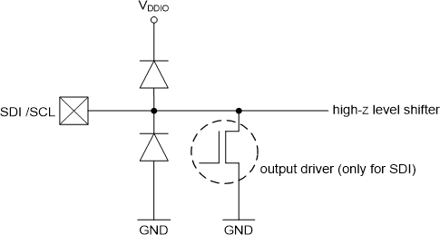
| 1 | VDDIO | Supply | Digital interface supply voltage (1.2V to 3.6V) |
| 2 | SCK | Input | Serial clock input (I2C SCL / SPI SCK) |
| 3 | VSS | Supply | Ground |
| 4 | SDI | In/Out | Serial data input (I2C SDA / SPI MOSI) |
| 5 | SDO | In/Out | Serial data output (SPI MISO / I2C address bit SA0) |
| 6 | CSB | Input | Chip select (SPI active-low / I2C not used, tie high) |
| 7 | INT | Output | Interrupt output (data ready, FIFO watermark, FIFO full) |
| 8 | VSS | Supply | Ground |
| 9 | VSS | Supply | Ground |
| 10 | VDD | Supply | Analog supply voltage (1.65V to 3.6V) |
Absolute Maximum Ratings
| Parameter | Min | Max | Unit |
|---|---|---|---|
| Voltage at VDD / VDDIO pin | -0.3 | 3.6 | V |
| Voltage at any interface pin | VSS - 0.3 | VDDIO + 0.3 | V |
| Storage temperature (<=65% RH) | -45 | +85 | deg C |
| Overpressure survivability | -- | 2,000,000 | Pa |
| Mechanical shock (MIL-STD-883H) | -- | 20,000 | g |
| Max dust particle inside package | -- | 300 | um |
| ESD CDM | -- | 500-750V | Class C2a |
| ESD HBM | -- | 2 kV | Class 2 |
Electrical Characteristics
| Parameter | Conditions | Min | Typ | Max | Unit |
|---|---|---|---|---|---|
| Supply voltage VDD | -- | 1.65 | 1.8 | 3.6 | V |
| Interface voltage VDDIO | -- | 1.2 | 1.8 | 3.6 | V |
| Operating temperature | Full accuracy | 0 | -- | +65 | deg C |
| Operating pressure | Full accuracy | 300 | -- | 1250 | hPa |
| Relative accuracy (700-1100 hPa, 25-40 deg C) | 10 kPa steps | -- | +/-0.03 | -- | hPa |
| Absolute accuracy (300-1100 hPa, 0-65 deg C) | @ 900 hPa, 25 deg C | -- | -- | +/-0.50 | hPa |
| Absolute accuracy (900-1100 hPa, 25-40 deg C) | -- | -- | -- | +/-0.40 | hPa |
| Offset temperature coefficient | 900 hPa, 25-40 deg C | -- | +/-0.62 | -- | Pa/K |
| Pressure resolution (highest mode) | -- | -- | 0.016 | -- | Pa |
| RMS noise (lowest BW, highest res) | -- | -- | 0.02 | -- | Pa |
| Temperature accuracy | @ 25 deg C | -- | -- | +/-0.5 | deg C |
| Temperature accuracy | 0 to +65 deg C | -- | -- | +/-1.5 | deg C |
| Long-term stability (12 months) | -- | -- | -- | +/-0.16 | hPa |
| Solder drift | Min 50 um solder height | -- | -- | +/-0.8 | hPa |
| Start-up time | VDD/VDDIO > 1.8V | -- | -- | 2 | ms |
| Max sampling rate | osrs_t = osrs_p = 1 | -- | -- | 200 | Hz |
| ODR accuracy | -- | -12 | -- | +12 | % |
Power Consumption
| Parameter | Conditions | Typ | Max | Unit |
|---|---|---|---|---|
| Sleep current | VDD = VDDIO = 1.8V | 1.4 | -- | uA |
| Sleep current | VDD = VDDIO = 3.6V | 1.5 | -- | uA |
| Peak current (pressure) | During P measurement | 660 | 730 | uA |
| Peak current (temperature) | During T measurement | 240 | 320 | uA |
| Handheld low-power (x8 P, x1 T, IIR=2) | Normal mode, 12.5 Hz | 145 | -- | uA |
| Handheld dynamic (x4 P, x1 T, IIR=4) | Normal mode, 50 Hz | 310 | -- | uA |
| Weather monitoring (x1 P, x1 T, no IIR) | Forced mode, 1/60 Hz | 4 | -- | uA |
| Drop detection (x2 P, x1 T, no IIR) | Normal mode, 100 Hz | 358 | -- | uA |
| Indoor navigation (x16 P, x2 T, IIR=4) | Normal mode, 25 Hz | 560 | -- | uA |
| Drone (x8 P, x1 T, IIR=2) | Normal mode, 50 Hz | 570 | -- | uA |
Communication Interface
The BMP390 supports two digital interfaces selected via the CSB pin state at power-on:
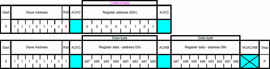
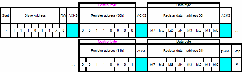
I2C Interface supports standard mode (up to 400 kHz), fast mode, and high-speed mode (up to 3.4 MHz). The 7-bit slave address is 0x76 when SDO is connected to GND, or 0x77 when SDO is connected to VDDIO. Multi-byte burst reads with auto-incrementing address are supported.
SPI Interface supports 3-wire and 4-wire modes at up to 10 MHz clock frequency. SPI mode is selected when CSB is toggled during power-on. The MSB of the register address byte is the R/W bit (0 = write, 1 = read). A dummy byte follows the address byte on reads before data is returned.
| Parameter | I2C | SPI |
|---|---|---|
| Max clock frequency | 3.4 MHz | 10 MHz |
| Address / mode selection | SDO pin (0x76 / 0x77) | CSB toggle at boot |
| Wire count | 2 (SCL, SDA) | 3 or 4 (SCK, SDI, SDO, CSB) |
| Burst read | Yes (auto-increment) | Yes (auto-increment) |
| Internal CSB pull-up | 75-125 kOhm | 75-125 kOhm |
Packages
| Package | Pins | Body Size | Height |
|---|---|---|---|
| Metal-lid LGA | 10 | 2.0 x 2.0 mm | 0.75 mm (max 0.80 mm) |
Pad dimensions: 0.275 x 0.250 mm (6 pads), 0.250 x 0.275 mm (4 pads). Pin 1 indicator on top-right corner (top view). Vent hole diameter 0.250 mm on top surface. Tape and reel packaging: 10,000 pcs per reel, 2.0 mm pitch.
Software API
The BMP390 register map starts at address 0x00 (CHIP_ID = 0x60) and extends to 0x7E (CMD). Key registers:
| Register | Address | Function |
|---|---|---|
| CHIP_ID | 0x00 | Chip identification (0x60) |
| ERR_REG | 0x02 | Error flags (fatal, cmd, conf) |
| STATUS | 0x03 | Data ready flags |
| DATA_0..2 | 0x04-0x06 | 24-bit pressure data |
| DATA_3..5 | 0x07-0x09 | 24-bit temperature data |
| SENSORTIME | 0x0C-0x0E | 24-bit sensor time counter |
| INT_STATUS | 0x11 | Interrupt status (drdy, fwm, ffull) |
| FIFO_LENGTH | 0x12-0x13 | FIFO byte counter (9-bit) |
| FIFO_DATA | 0x14 | FIFO data output |
| FIFO_WTM | 0x15-0x16 | FIFO watermark threshold |
| FIFO_CONFIG_1 | 0x17 | FIFO mode, stop-on-full, channel enable |
| FIFO_CONFIG_2 | 0x18 | FIFO subsampling, data select |
| INT_CTRL | 0x19 | Interrupt config (level, OD, latch, enable) |
| IF_CONF | 0x1A | Interface config (SPI3, I2C WDT) |
| PWR_CTRL | 0x1B | Power mode, press/temp enable |
| OSR | 0x1C | Oversampling for pressure and temperature |
| ODR | 0x1D | Output data rate prescaler |
| CONFIG | 0x1F | IIR filter coefficient |
| Calibration | 0x31-0x45 | NVM trimming coefficients (T1-T3, P1-P11) |
| CMD | 0x7E | Command register (soft reset = 0xB6) |
Power modes are controlled via PWR_CTRL[1:0]: 00 = sleep, 01/10 = forced (single-shot), 11 = normal (continuous). Oversampling is set via OSR register: osr_p[2:0] for pressure (1x to 32x) and osr_t[5:3] for temperature (1x to 32x).
Bosch Sensortec provides an official open-source API driver: BMP3-Sensor-API on GitHub.
Applications
- Indoor navigation and localization (floor detection, elevator detection)
- Enhancement of GPS navigation (time-to-first-fix, dead-reckoning, slope detection)
- Vertical velocity indication (rise/sink speed for drones and flying toys)
- Drone altitude hold and precision barometric sensing
- Weather monitoring and forecasting (home weather stations)
- Health care applications (spirometry)
- Fitness applications (calorie detection enhancement via altitude changes)
- AR and VR applications
- Context awareness and activity recognition
- Drop detection
- Target devices: smartphones, tablets, GPS modules, wearables, watches, navigation systems, white goods
Key Formulas
IIR Filter
data_filtered = (data_filtered_old * filter_coefficient + data_ADC) / (filter_coefficient + 1)
Normal Mode Sampling Period
tau_sampling = prescaler / f_sampling
f_sampling = 200 Hz (base)
Temperature Compensation (floating point)
partial1 = uncomp_temp - PAR_T1
partial2 = partial1 * PAR_T2
t_lin = partial2 + (partial1 * partial1) * PAR_T3
compensated_temp = t_lin  (in degrees C)
Pressure Compensation (floating point)
out1 = PAR_P5 + PAR_P6*t_lin + PAR_P7*t_lin^2 + PAR_P8*t_lin^3
out2 = uncomp_press * (PAR_P1 + PAR_P2*t_lin + PAR_P3*t_lin^2 + PAR_P4*t_lin^3)
out3 = uncomp_press^2 * (PAR_P9 + PAR_P10*t_lin)
out4 = uncomp_press^3 * PAR_P11
compensated_press = out1 + out2 + out3 + out4  (in Pa)
Calibration Coefficient Conversion (NVM to float)
PAR_T1 = NVM_PAR_T1 / 2^(-8)
PAR_T2 = NVM_PAR_T2 / 2^30
PAR_T3 = NVM_PAR_T3 / 2^48
PAR_P1 = (NVM_PAR_P1 - 2^14) / 2^20
PAR_P2 = (NVM_PAR_P2 - 2^14) / 2^29
PAR_P3 = NVM_PAR_P3 / 2^32
PAR_P5 = NVM_PAR_P5 / 2^(-3)
PAR_P6 = NVM_PAR_P6 / 2^6