BMI323
UnreviewedBosch Sensortec BMI323 6-axis IMU — 16-bit accelerometer (±2/4/8/16g) and gyroscope (±125–2000°/s) with on-chip feature engine, SPI/I3C/I2C, 2.5×3.0mm LGA
Source: Bosch Sensortec Datasheet (BST-BMI323-DS000-12)
Manufacturer: Bosch Sensortec
Part Number: BMI323
Document: BST-BMI323-DS000-12 — Rev 1.6, August 28th 2025
Description
The BMI323 is a highly integrated, low-power inertial measurement unit (IMU) that combines precise acceleration and angular rate (gyroscopic) measurement with intelligent on-chip motion-triggered interrupt features. It integrates a 16-bit digital triaxial accelerometer with a configurable range of +/-2 g to +/-16 g, a 16-bit digital triaxial gyroscope with a configurable range of +/-125 deg/s to +/-2000 deg/s, and a 16-bit digital temperature sensor operating from -40 degC to +85 degC.
The device features an on-chip interrupt engine with integrated smart features for always-on applications including motion detection, step detection and counting, orientation and flat detection, and single/double/triple tap detection. A built-in power management unit (PMU) enables advanced power management with ultra-low current consumption of typically 790 uA in full ODR aliasing-free operation, and as low as 15 uA in suspend mode.
The BMI323 communicates via SPI (up to 10 MHz, 4-wire and 3-wire), I3C (up to 12.5 MHz), and I2C (up to 1 MHz Fm+). It includes a 2 KB on-chip FIFO buffer, hardware-synchronized sensor timestamps, rapid 2.5 ms startup time, and sub-1 ms group delay. The compact 2.5 x 3.0 mm LGA package with 0.83 mm height makes it ideal for space-constrained wearable, hearable, and mobile applications.
Key Specifications
| Parameter | Value |
|---|---|
| Accelerometer Range | +/-2 g, +/-4 g, +/-8 g, +/-16 g (selectable) |
| Gyroscope Range | +/-125, +/-250, +/-500, +/-1000, +/-2000 deg/s (selectable) |
| Resolution | 16-bit (accelerometer, gyroscope, temperature) |
| Output Data Rate | 0.78125 Hz to 6400 Hz |
| Supply Voltage (VDD) | 1.71 V to 3.63 V |
| Supply Voltage (VDDIO) | 1.08 V to 3.63 V |
| Current Consumption (Typ) | 790 uA (A+G high performance, max ODR) |
| Current Consumption (Suspend) | 15 uA |
| Interfaces | SPI (10 MHz), I3C (12.5 MHz), I2C (1 MHz Fm+) |
| Operating Temperature | -40 degC to +85 degC |
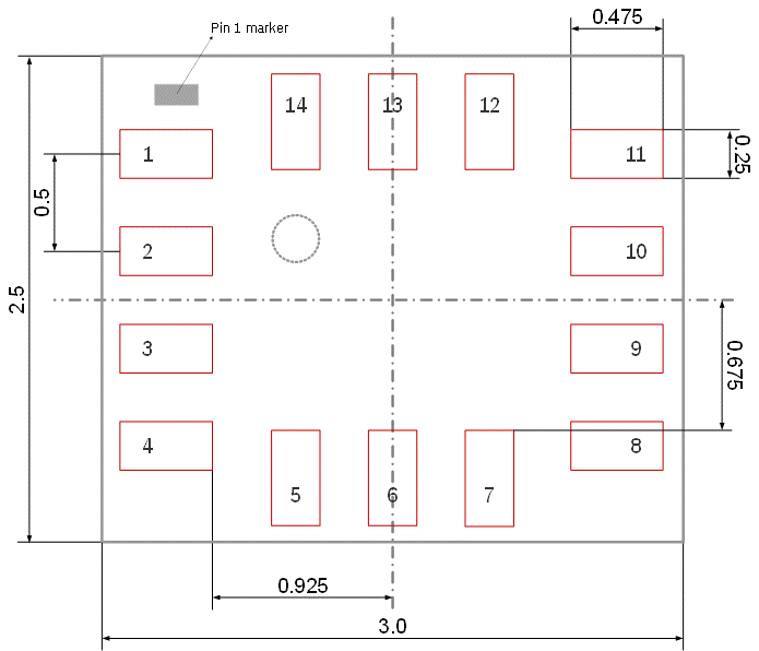
| Package | 2.5 x 3.0 x 0.83 mm LGA, 14 pins |
| FIFO Buffer | 2 KB |
| Accel Noise Density | 180 ug/sqrt(Hz) |
| Gyro Noise Density | 0.007 deg/s/sqrt(Hz) |
| Startup Time | 2.5 ms (accelerometer), 30 ms (gyroscope) |
Features
- 16-bit triaxial accelerometer with +/-2 g to +/-16 g configurable range
- 16-bit triaxial gyroscope with +/-125 to +/-2000 deg/s configurable range
- 16-bit temperature sensor (-40 degC to +85 degC)
- Ultra-low current consumption: 15 uA suspend, 45 uA accel-only low power, 790 uA full performance
- Rapid startup: 2.5 ms accelerometer (fast start), 30 ms gyroscope
- Sub-1 ms group delay
- 2 KB on-chip FIFO data buffer for accelerometer, gyroscope, temperature, and timestamps
- Hardware synchronization of accelerometer, gyroscope, and temperature (< 1 us)
- Sensor timestamps for accurate host-sensor time synchronization (< 40 us)
- Two independent programmable interrupt/synchronization I/O pins
- Built-in power management unit (PMU) with multiple power modes
- On-chip feature engine with motion detection (any-motion, no-motion, significant motion)
- Step detector and plug-and-play step counter
- Orientation and flat detection
- Single, double, and triple tap detection
- Tilt detection
- Fast offset and sensitivity error compensation
- Gyroscope self-calibration (CRT) with max sensitivity error < 1%
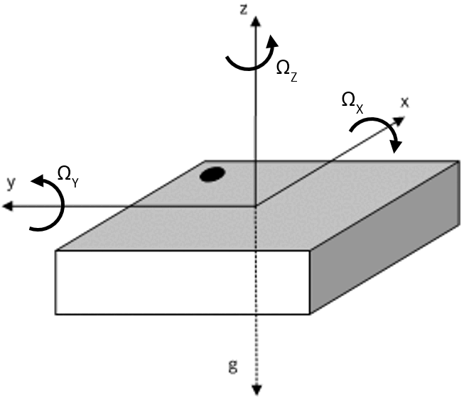
- Axis re-mapping and sign inversion
- Programmable low-pass filtering with configurable bandwidth
- Auto-operation mode change capability
- RoHS compliant, halogen-free, lead-free
Pin Configuration
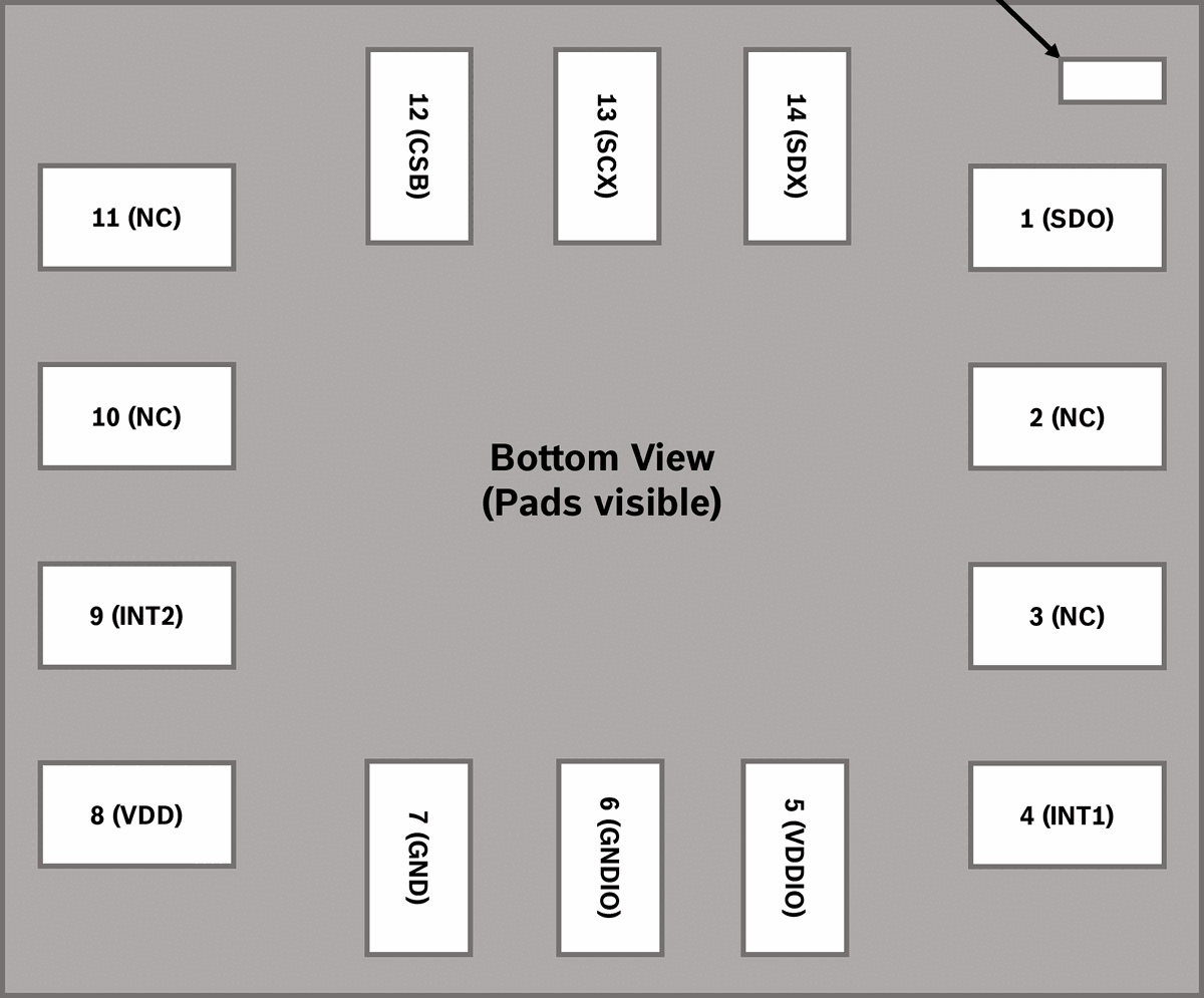
| Pin | Name | Type | Description |
|---|---|---|---|
| 1 | SDO | Digital I/O | Serial data output (SPI 4-wire); I2C address bit-0 select (I2C mode) |
| 2 | NC | Digital I/O | No connection (do not connect) |
| 3 | NC | Digital I/O | No connection (do not connect) |
| 4 | INT1 | Digital I/O | Interrupt pin 1 |
| 5 | VDDIO | Supply | Digital I/O supply voltage (1.08 V to 3.63 V) |
| 6 | GNDIO | Ground | Ground for I/O |
| 7 | GND | Ground | Ground for digital and analog |
| 8 | VDD | Supply | Power supply for analog and digital domain (1.71 V to 3.63 V) |
| 9 | INT2 | Digital I/O | Interrupt pin 2 |
| 10 | NC | -- | No connection (do not connect) |
| 11 | NC | -- | No connection (do not connect) |
| 12 | CSB | Digital in | Chip select for SPI mode; connect to VDDIO for I2C/I3C |
| 13 | SCx | Digital in | SCK for SPI serial clock; SCL for I2C/I3C serial clock |
| 14 | SDx | Digital I/O | SDI serial data input (SPI 4-wire); SDIO (SPI 3-wire); SDA (I2C/I3C) |
Absolute Maximum Ratings
| Parameter | Min | Max | Unit |
|---|---|---|---|
| Voltage at VDD Pin | -0.3 | 4 | V |
| Voltage at VDDIO Pin | -0.3 | 4 | V |
| Voltage at Non-Supply Pin | -0.3 | VDDIO + 0.3 (max 4) | V |
| Passive Storage Temperature | -50 | 150 | degC |
| OTP NVM Data Retention (at 85 degC) | 10 | -- | years |
| Mechanical Shock (MIL-STD-883K Cond. E) | -- | 10000 | g |
| Mechanical Shock (MIL-STD-883K Cond. F) | -- | 20000 | g |
| ESD HBM (JESD22-A114F, Class 2) | -- | 2000 | V |
| ESD CDM (JESD22-C101E, Class C2) | -- | 500 | V |
| ESD MM (JESD22-A115) | -- | 200 | V |
Electrical Characteristics
| Parameter | Conditions | Min | Typ | Max | Unit |
|---|---|---|---|---|---|
| Supply Voltage VDD | Core domain | 1.71 | 1.8 | 3.63 | V |
| Supply Voltage VDDIO | I/O domain | 1.08 | 1.2 | 3.63 | V |
| Input Low Voltage (VIL) | SPI, I2C, I3C | -- | -- | 0.3 x VDDIO | V |
| Input High Voltage (VIH) | SPI, I2C, I3C | 0.7 x VDDIO | -- | -- | V |
| Output Low Voltage (VOL) | SPI | -- | -- | 0.2 x VDDIO | V |
| Output High Voltage (VOH) | SPI | 0.8 x VDDIO | -- | -- | V |
| Accel Sensitivity (2g) | -- | -- | 16384 | -- | LSB/g |
| Accel Sensitivity (4g) | -- | -- | 8192 | -- | LSB/g |
| Accel Sensitivity (8g) | -- | -- | 4096 | -- | LSB/g |
| Accel Sensitivity (16g) | -- | -- | 2048 | -- | LSB/g |
| Accel Sensitivity Error | Soldered, over lifetime, best fit | -- | +/-0.5 | -- | % |
| Accel Zero-g Offset | Soldered | -- | +/-35 | -- | mg |
| Accel Zero-g Offset (over lifetime) | Soldered, over lifetime | -- | +/-50 | -- | mg |
| Accel Noise Density | HP mode, 8g range | -- | 180 | -- | ug/sqrt(Hz) |
| Accel Nonlinearity | Best fit, 2g range | -- | 0.1 | -- | %FS |
| Gyro Sensitivity (2000 deg/s) | -- | -- | 16.384 | -- | LSB/(deg/s) |
| Gyro Sensitivity (125 deg/s) | -- | -- | 262.144 | -- | LSB/(deg/s) |
| Gyro Sensitivity Error (with CRT) | Soldered, over lifetime, after self-cal | -- | +/-0.7 | -- | % |
| Gyro Zero Rate Offset | Soldered, over lifetime | -- | +/-1 | -- | deg/s |
| Gyro Noise Density | HP mode | -- | 0.007 | -- | deg/s/sqrt(Hz) |
| Gyro Nonlinearity | Best fit, 2000 deg/s | -- | 0.15 | -- | % |
| Power On Time | Supply on to serial I/F operational | -- | 0.0037 | -- | ms |
| ODR Accuracy (Accel) | -- | -- | +/-1.7 | -- | % |
| ODR Accuracy (Gyro) | -- | -- | +/-2 | -- | % |
Power Consumption
| Mode | Accel Config | Gyro Config | Typical Current (uA) |
|---|---|---|---|
| Suspend | Disabled | Disabled | 15 |
| Accel-only Low Power | LP, 25 Hz | Disabled | 45 |
| Accel-only High Performance | HP, max ODR | Disabled | 145 |
| A+G High Performance | HP, max ODR | HP, max ODR | 790 |
| A+G Normal | Normal, max ODR | Normal, max ODR | 690 |
| A+G Low Power | LP, 25 Hz | LP, 25 Hz | 390 |
| Gyroscope Drive Only | Disabled | Drive only | 1500 |
Communication Interface
The BMI323 supports three digital communication interfaces, selectable via pin configuration at power-up:
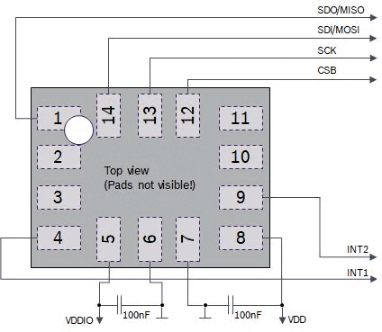
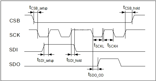
SPI (Serial Peripheral Interface): Supports both 4-wire and 3-wire SPI modes with a maximum clock frequency of 10 MHz. In 4-wire mode, pins CSB (chip select), SCK (clock), SDI (data in), and SDO (data out) are used. In 3-wire mode, SDI and SDO are combined on a single bidirectional SDIO line. The first byte of each transaction contains the read/write bit and the 7-bit register address. A dummy byte is required after the address byte for read operations.
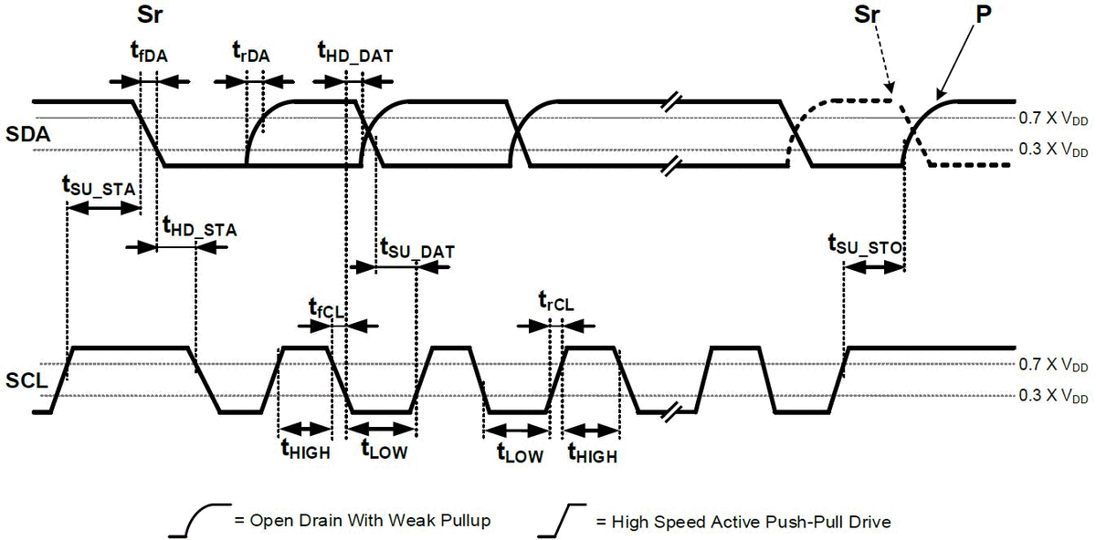
I3C (Improved Inter-Integrated Circuit): Supports MIPI I3C SDR mode at up to 12.5 MHz. The device supports both private read/write operations and common command codes (CCC). I3C uses pins SCL (clock) and SDA (data) with open-drain and push-pull drive modes. The device includes an I3C provisional identifier for dynamic address assignment.
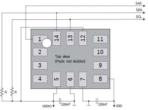
I2C (Inter-Integrated Circuit): Supports I2C Fast Mode Plus (Fm+) at up to 1 MHz. The 7-bit I2C slave address is determined by the SDO pin level: 0x68 when SDO is connected to GND, or 0x69 when SDO is connected to VDDIO. Uses pins SCL (clock) and SDA (data) with open-drain configuration requiring external pull-up resistors.
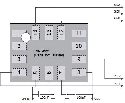
All interfaces use 16-bit (word) register access. It is recommended to use 100 nF decoupling capacitors at the VDDIO (pin 5) and VDD (pin 8) supply pins.
Packages
| Parameter | Value |
|---|---|
| Package Type | LGA (Land Grid Array) overmold |
| Dimensions | 2.5 x 3.0 x 0.83 mm |
| Pin Count | 14 |
| Moisture Sensitivity Level | JEDEC Level 1 |
| Soldering | Lead-free reflow, peak temperature up to 260 degC |
| Compliance | RoHS (2011/65/EU), halogen-free, lead-free |
| Sales Part Number | 0 273 017 028 |
Software API
Bosch Sensortec provides the BMI3 Sensor API, an open-source C driver available on GitHub (github.com/boschsensortec/BMI323_SensorAPI). The API abstracts register-level access and provides high-level functions for:
- Device initialization and configuration
- Accelerometer and gyroscope data readout
- FIFO buffer management and data parsing
- Feature engine configuration (motion detection, step counter, tap detection, orientation, tilt, flat detection)
- Self-test and self-calibration (CRT) procedures
- Interrupt configuration and mapping
- Axis re-mapping and offset/sensitivity compensation
- Power mode management
The API follows a hardware-abstraction-layer (HAL) pattern where users provide platform-specific SPI/I2C read/write and delay callback functions. Configuration is performed through structured types for each sensor and feature, making it straightforward to integrate into embedded applications. The feature set can be optimized for wearable, hearable, and mobile application profiles via the API.
Applications
- Wearable devices (fitness trackers, smartwatches)
- Hearable devices (smart earbuds, hearing aids)
- Smartphones and mobile devices
- Activity and gesture recognition
- Step counting and pedometer applications
- Dead reckoning and indoor navigation
- Orientation and tilt detection
- Image stabilization
- Robotics and drone stabilization
- Gaming controllers and motion input devices
- IoT sensor nodes
- Always-on motion-triggered wake-up systems
Key Formulas
Accelerometer output conversion to physical units:
Acceleration [g] = ACC_DATA / Sensitivity
  where Sensitivity = 16384 LSB/g (2g range)
                    = 8192 LSB/g  (4g range)
                    = 4096 LSB/g  (8g range)
                    = 2048 LSB/g  (16g range)
Gyroscope output conversion to physical units:
Angular Rate [deg/s] = GYR_DATA / Sensitivity
  where Sensitivity = 262.144 LSB/(deg/s) (125 deg/s range)
                    = 131.072 LSB/(deg/s) (250 deg/s range)
                    = 65.536 LSB/(deg/s)  (500 deg/s range)
                    = 32.768 LSB/(deg/s)  (1000 deg/s range)
                    = 16.384 LSB/(deg/s)  (2000 deg/s range)
Temperature sensor conversion:
Temperature [degC] = (TEMP_DATA / 512) + 23
User offset compensation (accelerometer):
Compensated_Output = Raw_Output + User_Offset
  where User_Offset is programmed via ACC_OFF_X/Y/Z registers
  Resolution: 1 LSB = 0.0039 mg (at 2g range)
Flat detection angle threshold:
theta [deg] = arctan(value / 64) * (180 / pi)
  where value is the register value (0-63)