BME690 Molecule v9352035
Unreviewed15×15 mm breakout for the Bosch BME690 combined temperature / humidity / pressure / gas sensor. I²C at 0x76 via JP1 SDO→GND bridge.
BME690 Molecule — Hardware Reference
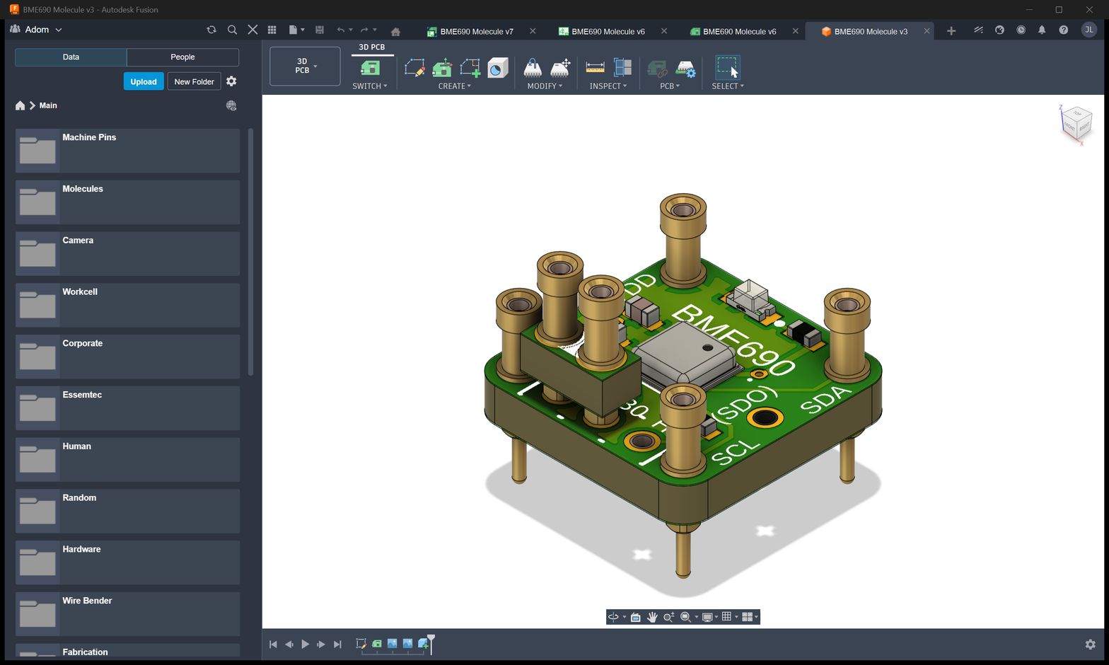
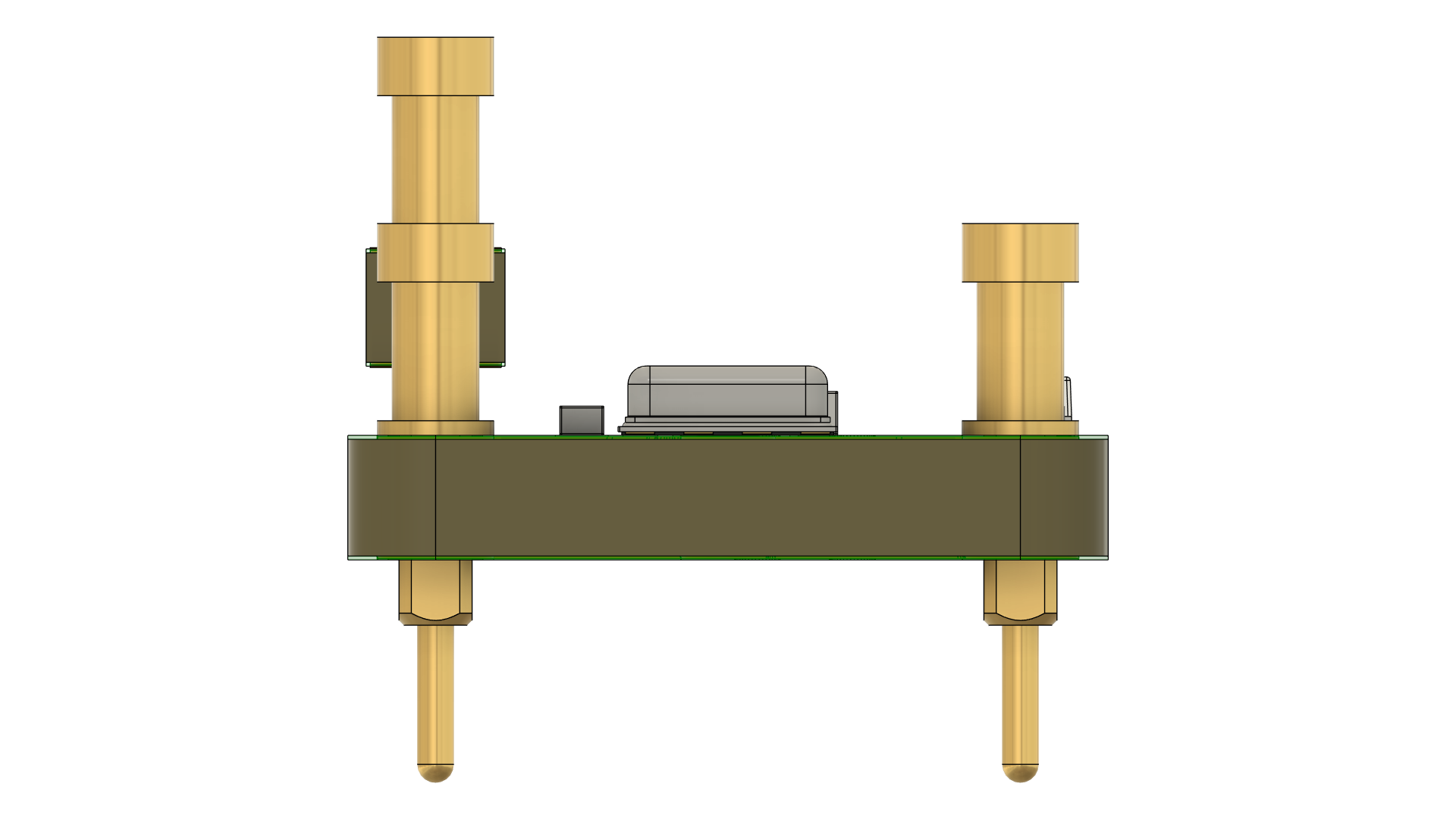
Small (~15×15 mm) 4-corner-pin breakout for the Bosch BME690 combined temperature / humidity / pressure / gas sensor.
- Source: Fusion Electronics project (not on GitHub). Published assets live on the wiki.
- Wiki page: molecules/bme690-molecule-v9352035-912960
- Board: 4 corner through-hole mount-pins + 1 side castellation for the SDO address strap, plus on-board jumper
- IC: BME690 (Bosch LGA-8, 3.0 × 3.0 × 0.93 mm, IC1)
- Silk title:
BME690centered on the package
Component summary (from Fusion BOM bom.csv)
| Ref | Part | Footprint | Function |
|---|---|---|---|
| IC1 | BME690 | BME690 (LGA-8) | Combined T / RH / P / gas sensor |
| C1, C2 | 100 nF 0402 | CAPC1005X60 | VDD / VDDIO decoupling |
| R1, R2 | 0402 | RESC1005X40 | SDO address-strap resistors (one to VDD, one to GND — DNP-paired to hard-set the default, JP1 lets the user override) |
| D1 | LED 0603 | LED_KT-0603-WHITE | Power / status indicator |
| JP1 | 3×1 jumper | 3X1_JUMP |
SDO / I²C-address strap (see below) |
| GND/SCL/SDA/VDD | machine pins | MACH_PIN_MED_SHORT |
External interface |
| SDO | castellation | CONTACT_MED |
SDO test-point (also routed to JP1) |
| U$1 | Adom Icon | ADOM_ICON-4MM |
Silk/logo only |
External contact map
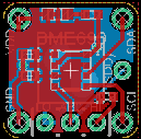
4 corner through-hole pins for the primary interface, plus one side castellation for the SDO test-point. Silk labels are visible in the Fusion renders at molecules/bme690-molecule-v9352035-912960 (3d-home.png, 3d-board.png):
| Silk | Role |
|---|---|
VDD (or 3.3V) |
VDD + VDDIO (shared) — 1.71–3.6 V |
GND |
Ground |
SDA |
I²C SDA |
SCL |
I²C SCL |
SDO (castellation, labelled (SDO)) |
Address strap — connect via JP1 |
Note: the BOM lists the four mount-pin pads generically as
GND SCL SDA VDD. Silk position matches the Fusion 3D render —VDDtop-left,GNDbottom-left,SDAright,SCLbottom-middle/right.
I²C address strap (JP1)
The BME690's I²C address is set by the SDO pin at power-up:
| JP1 position | SDO tied to | I²C address |
|---|---|---|
| 1–2 bridged (SDO → GND) | GND | 0x76 (demo firmware target ✓, Bosch default) |
| 2–3 bridged (SDO → VDD) | VDD | 0x77 |
Firmware expects 0x76 — verify JP1 is bridged on the GND side before flashing. If you see a probe NACK at 0x76 but the chip ACKs at 0x77, the jumper is on the wrong side.
Interface
I²C only on this breakout — there is no exposed CSB pad (the chip's SPI interface is tied off on-board). The BME690 package can do SPI, but this molecule doesn't bring those pads out.
Power
| Rail | Voltage | Source |
|---|---|---|
| VDD / VDDIO | 1.71–3.6 V (3.3 V in demo) | Host via the VDD pin |
Single rail. Typical active current 2.1 mA during a gas-sensor measurement burst (heater on), < 100 µA idle. Budget for peak current on the 3.3 V rail accordingly.
Wiring to the Stationary RM2 I²C bus
BME690 VDD  ──── RM2 +3V3
BME690 GND  ──── RM2 GND
BME690 SDA  ──── RM2 GPIO4 (I²C0 SDA)
BME690 SCL  ──── RM2 GPIO5 (I²C0 SCL)
BME690 SDO  ──── (typically left floating; JP1 sets the address on-board)
Bridge JP1 on the GND side so SDO → GND → address 0x76.
Gotchas for firmware bring-up
- JP1 must be bridged on the GND side for the 0x76 probe to succeed. Default from-the-factory state may be open (floating SDO → indeterminate address).
- 4.7 kΩ I²C pull-ups are off-board (provided by the stationary RM2 carrier).
- Gas sensor heater draws ~2 mA during the burn. Make sure the +3V3 rail can source that without sagging (C1/C2 handle the transient; the upstream LDO needs enough headroom).
- BSEC2 library is required for calibrated IAQ / gas-index output — currently a TODO in
firmware/sensors/bme690.c. Without BSEC2 the firmware returns raw gas resistance only. - BME690 calibration trim registers (0x8A, 0xE1) are read by the driver at init — no external action needed.
Known gaps in this doc
The .fsch / .fbrd Fusion source files are attached to the wiki page but the wiki server currently returns 404 on design-file downloads (design files aren't publicly served — only images / BOM / CPL). As a result the exact JP1 default solder state, R1/R2 populated-vs-DNP status, and the precise silk coordinates couldn't be verified here. If you own the Fusion project, export a .kicad_* set and drop it under /bosch-molecules/BME690/ to unblock a full netlist extraction.