BHI360
UnreviewedBosch Sensortec BHI360 programmable, ultra-low-power smart sensor hub with integrated 6-axis IMU (accelerometer + gyroscope), 32-bit Fuser2 MCU, and BSX sensor fusion library. 2.5x3.0mm LGA-20 package
Source: Bosch Sensortec Datasheet (BST-BHI360-DS000-03)
Manufacturer: Bosch Sensortec
Part Number: BHI360
Document: BST-BHI360-DS000-03 --- Rev 1.2, January 13, 2025
Description
The BHI360 is a highly integrated, ultra-low-power, programmable smart sensor system designed for always-on sensor data processing. It combines a best-in-class 6-axis IMU (16-bit 3-axis accelerometer and 16-bit 3-axis gyroscope) with a programmable 32-bit microcontroller (Fuser2) and an additional ultra-low-power custom core optimized for accelerometer-based always-on algorithms. The device includes a powerful software framework, SDK, and preinstalled sensor data processing algorithms including the BSX sensor fusion library.
Integrated in a compact 2.5 mm x 3.0 mm LGA package with 20 pads, the BHI360 is pin-to-pin backward compatible with many Bosch Sensortec IMUs, enabling easy replacement and platform design. It features a host interface configurable as SPI or I2C, two secondary master interfaces for connecting external sensors, up to 8 GPIOs, and fast I/O operations (SPI/GPIO up to 50 MHz, I2C up to 3.4 MHz).
The Fuser2 MCU core is based on ARC EM4 architecture delivering up to 3.67 CoreMark/MHz, with 256 kByte on-chip SRAM, 144 kByte on-chip ROM preloaded with software, and a 4-channel micro DMA controller. The integrated event-driven software framework with OPENRTOS multithreading kernel and virtual sensor stack provides a flexible platform for custom embedded algorithm development. The device supports high performance mode as well as several low-power modes including deep sleep at 7.8 uA.
Key Specifications
| Parameter | Value |
|---|---|
| IMU Type | 6-axis (3-axis accelerometer + 3-axis gyroscope) |
| Accelerometer Resolution | 16-bit |
| Gyroscope Resolution | 16-bit |
| Accelerometer Range | +/-2g, +/-4g, +/-8g, +/-16g (selectable) |
| Gyroscope Range | +/-125, +/-250, +/-500, +/-1000, +/-2000 deg/s (selectable) |
| Accelerometer ODR (Host) | 12.5 Hz to 800 Hz |
| Gyroscope ODR (Host) | 12.5 Hz to 800 Hz |
| MCU Core | ARC EM4, 3.67 CoreMark/MHz |
| MCU Frequency | 20 MHz (Long Run) / 50 MHz (Turbo) |
| On-chip SRAM | 256 kByte |
| On-chip ROM | 144 kByte |
| Supply Voltage VDD | 1.71 V to 3.6 V |
| Supply Voltage VDDIO | 1.71 V to 1.89 V (typ. 1.8 V) |
| Deep Sleep Current | 7.8 uA (typ.) |
| Long Run CoreMark Current | 950 uA @ 20 MHz |
| Turbo CoreMark Current | 2.8 mA @ 50 MHz |
| Operating Temperature | -40 to +85 deg C |
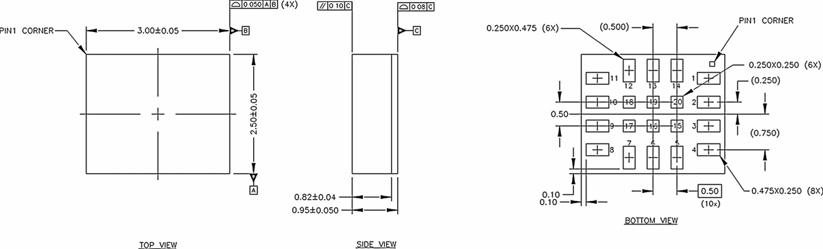
| Package | 2.5 mm x 3.0 mm x 0.95 mm LGA, 20 pads |
| Host Interface | SPI (up to 50 MHz) or I2C (up to 3.4 MHz) |
Features
- Best-in-class 6-axis IMU with 16-bit accelerometer and 16-bit gyroscope
- Programmable 32-bit Fuser2 MCU (ARC EM4) with FPU, running at 20 MHz or 50 MHz
- Ultra-low-power custom core (Bosch Sensortec Core) optimized for always-on algorithms
- 256 kByte on-chip SRAM and 144 kByte on-chip ROM with preloaded software
- 4-channel micro DMA controller and Memory Protection Unit (MPU)
- Integrated BSX sensor fusion library with 6DoF/9DoF orientation, gravity vector, and dynamic offset autocalibration
- Event-driven software framework with OPENRTOS multithreading real-time kernel
- Virtual sensor stack supporting step counter, tap detection, gesture detection, activity recognition, and wrist wear wake-up
- Host interface configurable as SPI (up to 50 MHz) or I2C (up to 3.4 MHz)
- Two secondary master interfaces (I2C and/or SPI) for external sensor expansion
- Up to 8 software-configurable GPIOs
- Secure boot mode with digital signature verification
- Pin-to-pin backward compatible with many Bosch Sensortec IMUs
- Deep sleep current as low as 7.8 uA with RAM retention
- Open sensor platform with SDK for custom embedded algorithm development
- Standard C library (libc) and math library (libm) available
Pin Configuration
| Pin | Name | Type | Description |
|---|---|---|---|
| 1 | HSDO | Input, Pull-down | Host Interface: SPI MISO / I2C address select |
| 2 | ASDX | Input, Pull-up | Sensor Aux Interface: OIS SDA / I2C SDA / Master 2 SPI MOSI or I2C SDA |
| 3 | ASCX | Input, Pull-up | Sensor Aux Interface: OIS Clock / I2C SCL / Master 2 SPI SCK or I2C SCL |
| 4 | HIRQ | Output | Host Interrupt Signal |
| 5 | VDDIO | Supply | Digital IO and Fuser2 Supply |
| 6 | GNDIO | Ground | Digital IO and Fuser2 Ground |
| 7 | GND | Ground | Analog Sensor Ground |
| 8 | VDD | Supply | Analog Sensor Supply |
| 9 | VREG | Supply | Voltage regulator output |
| 10 | OCSB | Input, Pull-up | Sensor Aux Interface: OIS Chip Select / Master 2 SPI CS1 |
| 11 | OSDO | Input, Pull-up | Sensor Aux Interface: OIS MISO / Master 2 SPI MISO |
| 12 | HCSB | Input, Pull-up | Host Interface: SPI Chip Select / I2C mode select (keep high for I2C) |
| 13 | HSCX | Input, Pull-up | Host Interface: SPI SCK / I2C SCL |
| 14 | HSDX | Input, Pull-up | Host Interface: SPI MOSI / I2C SDA |
| 15 | M3SCL | Input, Pull-up | Master 3 I2C SCL / Fuser2 Debug Clock (JTAG_CLK) |
| 16 | JTAG_DIO | Input, Pull-up | Fuser2 Debug Data (JTAG_DIO) |
| 17 | RESETN | Input, Pull-up | Reset input, active low |
| 18 | M3SDA | Input, Pull-up | Master 3: I2C SDA |
| 19 | RESV2 | Input, Pull-up | Reserved: do not connect (internal IMU interrupt) |
| 20 | RESV1 | Input, Pull-up | Reserved: do not connect (internal IMU interrupt) |
Absolute Maximum Ratings
| Parameter | Condition | Min | Max | Unit |
|---|---|---|---|---|
| Voltage at Supply Pin (VDD) | - | -0.3 | 4 | V |
| Voltage at Supply Pin (VDDIO) | - | -0.3 | 2.75 | V |
| Voltage at any Logic Pin | Non-supply pin | -0.3 | VDDIO+0.3 | V |
| Passive Storage Temp. Range | <=65% rel. humidity | -50 | 150 | deg C |
| NVM Data Retention | T = 85 deg C, after 15 cycles | 10 | - | years |
| NVM Write Cycles | - | - | 10,000 | cycles |
| Mechanical Shock (200 us half sine) | - | - | 2,900 | g |
| Mechanical Shock (0.3 ms half sine) | - | - | 2 | g |
| Free Fall onto Hard Surfaces | - | - | 2 | m |
| ESD (HBM) | - | - | 500 | kV |
| ESD (CDM) | - | - | 200 | V |
| ESD (MM) | - | - | 200 | V |
Electrical Characteristics
| Parameter | Symbol | Condition | Min | Typ | Max | Unit |
|---|---|---|---|---|---|---|
| Brown-out Detection Level (rising) | VBROUT-R | TA = -40 to 85 deg C | 1.3 | - | 1.6 | V |
| Voltage Input Low Level | VIL | - | - | - | 0.3*VDDIO | V |
| Voltage Input High Level | VIH | - | 0.7*VDDIO | - | - | V |
| Internal Pull-up (M3SCL) | RUPCLK | - | 35 | 61 | 107 | kOhm |
| Internal Pull-up (other pads) | RUP | - | 71 | 121 | 214 | kOhm |
| Internal Pull-down (HSDO) | RDN | - | 62 | 109 | 208 | kOhm |
| Pad Capacitance (Host IF pads) | CPAD1 | - | - | 1.8 | - | pF |
| Pad Capacitance (M3SCL) | CPAD2 | - | - | 3.6 | - | pF |
| Pad Capacitance (Aux IF pads) | CPAD3 | - | - | 6.8 | - | pF |
| System Oscillator (Long Run) | fSYSLR | TA = 25 deg C | 18.4 | 20 | 21.6 | MHz |
| System Oscillator (Turbo) | fSYST | TA = 25 deg C | 46 | 50 | 54 | MHz |
| Timer Oscillator Frequency | fTMR | TA = 25 deg C | 125 | 128 | 131 | kHz |
| Fuser2 CPU Benchmark | - | Metaware compiler | - | 3.67 | - | CoreMark/MHz |
Power Consumption
| Parameter | Condition | Typical Current | Unit |
|---|---|---|---|
| Deep Sleep | Gyro/Accel suspend, Fuser2 deep sleep, 32KB RAM retention | 7.8 | uA |
| Regular Sleep | Gyro/Accel suspend, Fuser2 regular sleep, 32KB RAM retention | 8.1 | uA |
| Accel Low Power Mode | Accel LP ODR 25Hz, Gyro suspend, Fuser2 deep sleep | 14 | uA |
| Accel Normal Mode | Accel normal, Gyro suspend, Fuser2 deep sleep | 214 | uA |
| Accel + Gyro Low Power | Accel+Gyro LP ODR 25Hz, Fuser2 deep sleep | 424 | uA |
| Accel + Gyro Normal | Accel+Gyro normal, ODR max, Fuser2 deep sleep | 689 | uA |
| Accel + Gyro Performance | Accel+Gyro performance, ODR max, Fuser2 deep sleep | 974 | uA |
| Fuser2 Long Run (matrix mult.) | Gyro/Accel suspend, 20 MHz | 840 | uA |
| Fuser2 Long Run (CoreMark) | Gyro/Accel suspend, 20 MHz | 950 | uA |
| Fuser2 Turbo (CoreMark) | Gyro/Accel suspend, 50 MHz | 2,800 | uA |
| Game Rotation Vector | IMU Normal, ODR 100 Hz | 784 | uA |
| Game Rotation Vector | IMU Low Power, ODR 25 Hz | 441 | uA |
| Rotation Vector (9DoF) | IMU Normal, ODR 100 Hz | 840 | uA |
| Wearable Activity Recognition | Accel Low Power | 43 | uA |
| Step Counter (wearable) | Accel Low Power | 45 | uA |
| No Motion / Any Motion | Accel Low Power | 32 | uA |
Communication Interface
The BHI360 host interface is configurable as either SPI or I2C. The mode is selected at boot time via the HCSB pin: pulling HCSB low selects SPI mode, keeping it high selects I2C mode.
I2C Mode:
- Supports standard mode (100 kHz), fast mode (400 kHz), fast mode plus (1 MHz), and high-speed mode (3.4 MHz)
- 7-bit addressing with address select via HSDO pin
- External pull-up resistors required on SDA and SCL lines connected to VDDIO
SPI Mode:
- 4-wire SPI with CPOL=0, CPHA=0 (SPI Mode 0)
- Maximum clock: 22 MHz (Long Run mode), 55 MHz (Turbo mode)
- Burst mode supported for efficient data transfer
Secondary Master Interfaces:
- Master Interface 2: Configurable as I2C or SPI for connecting external sensors (e.g., magnetometer)
- Master Interface 3: I2C-only interface for additional external sensors
- Both interfaces support connection of external sensors for 9DoF sensor fusion
Host Data Interface:
- 3 FIFO channels: Wake-Up FIFO, Non-Wake-Up FIFO, Status/Debug FIFO
- Configurable host interrupt (HIRQ) with edge or level trigger
- Command/response protocol for device configuration
- Parameter interface for runtime configuration changes
Packages
The BHI360 is available in a single package variant:
| Parameter | Value |
|---|---|
| Package Type | LGA (Land Grid Array) |
| Dimensions | 2.5 mm x 3.0 mm x 0.95 mm |
| Pad Count | 20 |
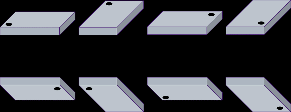
| Pin 1 Indicator | Dot marking on top surface |
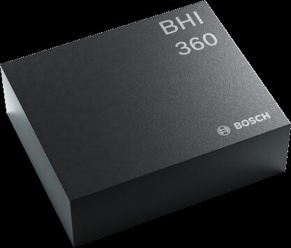
| Device Marking | VL CCC (V = product ID, L = internal code, CCC = tracing ID) |
| Sales Part Number | BHI360: 0 273 017 037 |
The package is designed for pin-to-pin backward compatibility with many Bosch Sensortec IMUs, enabling easy drop-in replacement on existing PCB designs. A recommended PCB footprint is provided in the datasheet.
Software API
The BHI360 includes a comprehensive integrated software stack accessible through its host interface register map and command protocol:
Event-Driven Software Framework:
- OPENRTOS multithreading real-time kernel
- Virtual sensor stack with configurable output data rates (1.56 Hz to 800 Hz)
- Wake-up and non-wake-up FIFO event channels for efficient data delivery
- Meta events for system status notifications (flush complete, sample rate changed, power mode changed, errors)
BSX Sensor Fusion Library:
- 6DoF and 9DoF 3D device orientation (quaternion, Euler angles)
- Gravity vector and linear acceleration
- Dynamic offset autocalibration for accelerometer, gyroscope, and magnetometer
- Geomagnetic rotation vector (with external magnetometer)
- Configurable high-performance or low-power fusion modes
Custom Core Algorithms (Bosch Sensortec Core):
- Step counter (wearable-optimized)
- Multi-tap detector (configurable single, double, triple tap)
- Wrist gesture detection and wrist wear wake-up
- Activity recognition (stationary, walking, running, etc.)
- Any motion / no motion / significant motion detection
SDK and Development:
- Open sensor platform for custom embedded algorithm development on Fuser2
- Standard C library (libc) and math library (libm)
- Digital signature libraries for secure boot
- Sensor data injection mode for algorithm testing
- Soft pass-through for direct access to secondary sensors
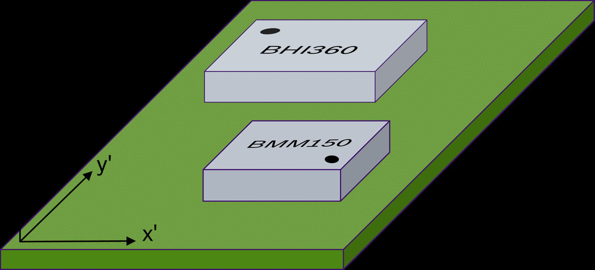
- Axis remapping via firmware configuration for flexible PCB placement
- Post-mortem debug data download for diagnostics
Host Interface Commands:
- Firmware upload to program RAM with boot command
- Sensor configuration (sample rate, dynamic range, FIFO format)
- Sensor self-test and fast offset compensation
- Parameter read/write interface for runtime configuration
Applications
- Wearable devices (smartwatches, fitness trackers, hearables, smart glasses)
- Smartphones, tablets, and mobile communication devices
- 24/7 always-on sensor data processing at ultra-low power
- Indoor navigation and pedestrian dead reckoning
- Gesture recognition and motion-controlled user interfaces
- Activity tracking and fitness monitoring
- Head tracking for AR/VR headsets
- IoT sensor hubs with external sensor expansion
- Robotics and drone stabilization
- Gaming controllers and motion input devices