AS5147 — 14-Bit On-Axis Magnetic Rotary Position Sensor
Unreviewedams OSRAM AS5147. 14-bit absolute / 11-bit incremental magnetic rotary sensor with DAEC™. SPI, ABI, UVW, PWM outputs. TSSOP-14, AEC-Q100 Grade 0 for BLDC motor commutation in EPS/transmission.
Source: ams OSRAM AS5147 Datasheet (DS000307)
Manufacturer: ams OSRAM (formerly AMS AG)
Part Number: AS5147
Document: DS000307, v2-00 — 2021-Jul-22 (14-Bit On-Axis Magnetic Rotary Position Sensor with 11-Bit Binary Incremental Pulse Count)
Description
The AS5147 is a 14-bit on-axis magnetic rotary position sensor with 11-bit binary incremental pulse count and supports high-speed operation. The rotary position sensor has been designed for high-speed commutation of BLDC motors.
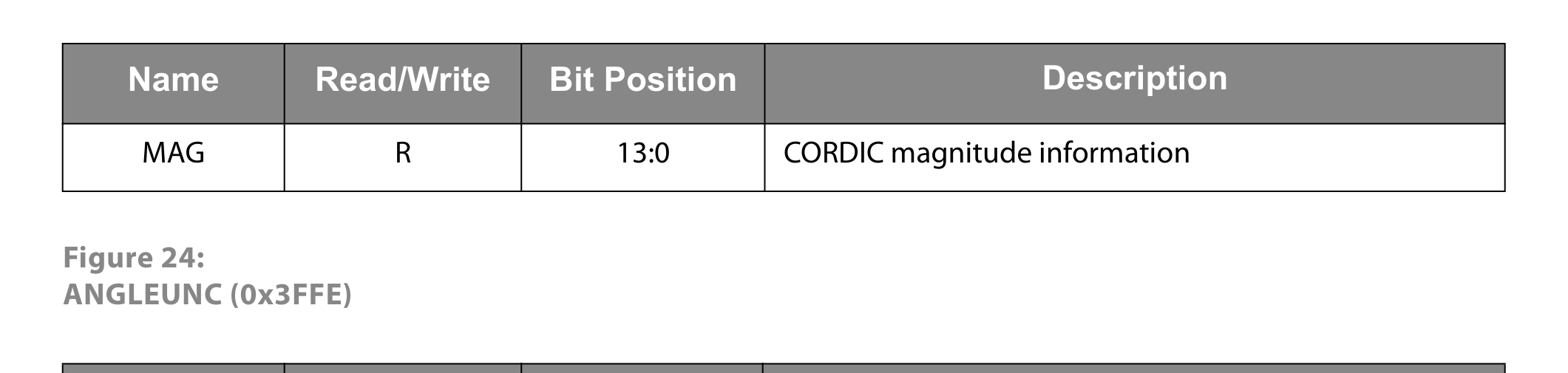
The magnetic field information of a diametric magnetized source (e.g. magnet) is sensed by integrated Hall sensors. A sophisticated hardwired CORDIC block (coordinate rotation digital computer) computes the angle and magnitude of the magnetic field vector. The angular data is internally filtered and temperature compensation algorithms are applied.
A standard 4-wire SPI serial interface allows a host microcontroller to read 14-bit absolute angle position data from the AS5147 and to program non-volatile settings without a dedicated programmer.
Standard incremental output signals ABI are provided along with PWM, UVW and commutation outputs for BLDC motor commutation. Diagnostic functions such as magnetic field strength and internal error recognition through CORDIC overflow, out-of-range, error flag, and cyclic redundancy check (CRC) are available.
The AS5147 is the first choice for the most demanding applications such as electric power steering (EPS), automotive actuators, and transmission control.
Key Specifications
| Parameter | Value |
|---|---|
| Core Resolution | 14-bit absolute |
| Incremental Resolution | 11-bit binary pulse count |
| Dynamic Angle Error Compensation | DAEC™ |
| Output Interfaces | SPI, ABI, UVW, PWM |
| Supply Voltage (VDD) | 5 V |
| Internal LDO (VDD3V3) | 3.3 V (external 1 µF decoupling required) |
| Max. Rotation Speed | Supports high-speed commutation |
| Qualifications | AEC-Q100 Grade 0 (automotive) |
| Package | TSSOP-14 |
| Operating Temperature (TaSV0) | −40 °C to 150 °C (in 5.0 V supply mode) |
| Operating Temperature (Ta3V3) | −40 °C to 125 °C (in 3.3 V supply mode, NOSSET = 0) |
Features
- DAEC™ Dynamic Angle Error Compensation
- 14-bit core resolution
- Independent output interfaces: SPI, ABI, UVW, PWM
- Zero position, configuration programmable
- Self-diagnostics
- Immune to external stray field
- No programmer needed (via SPI command)
- Supports safety-challenging applications
- Lower system costs (no shielding needed)
- Versatile choice of the interface
- Easy to use — saving costs on DSP
- Good resolution for motor and position control
Applications
- Electric power steering (EPS)
- Automotive transmission (gearbox, actuator)
- Pump
- Brake (actuator)
- Starter and alternator
- AEC-Q100 Grade 0 automotive qualified
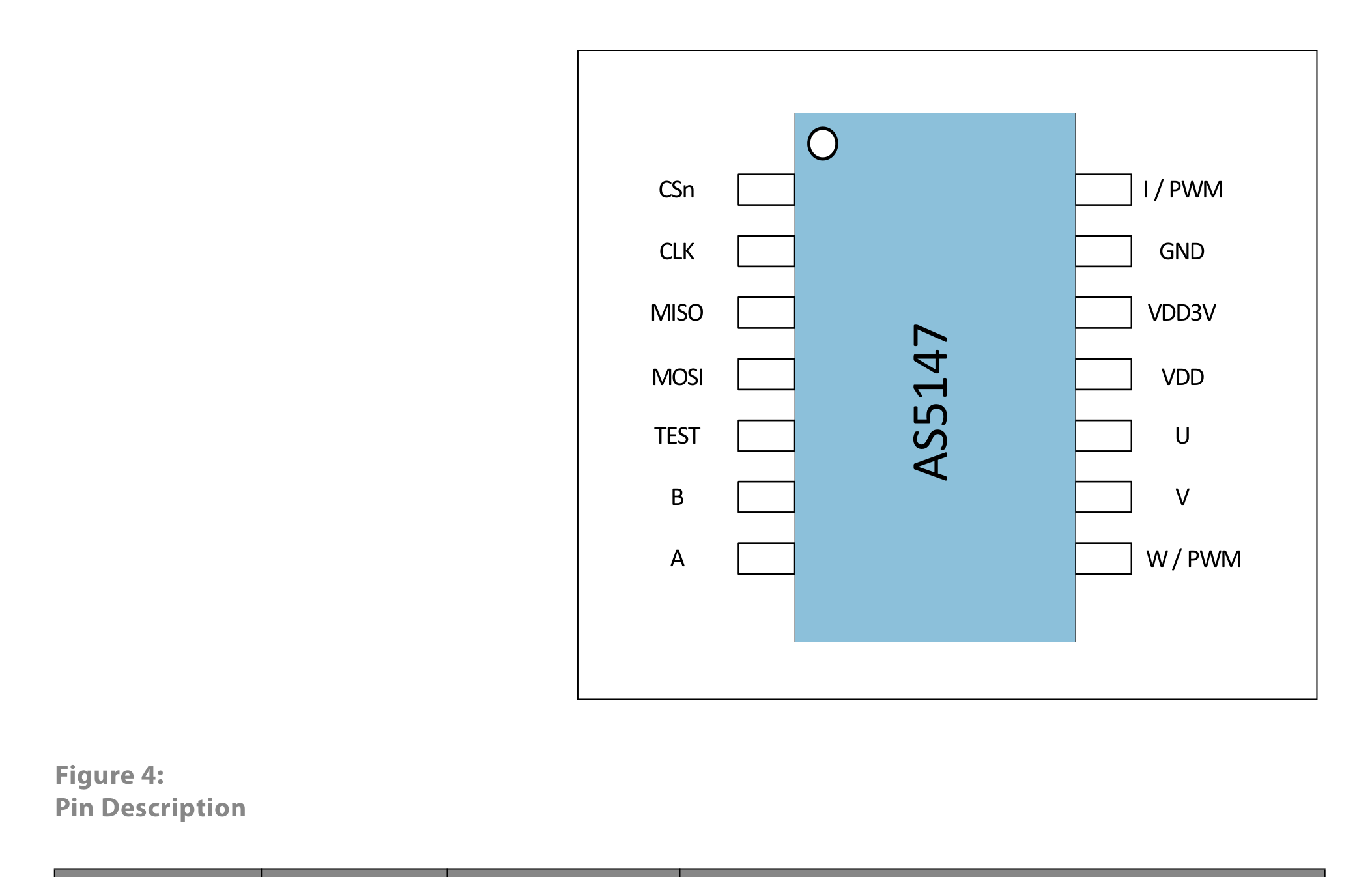
Pin Configuration
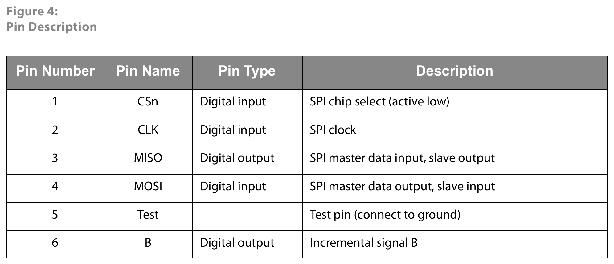
Package: TSSOP-14.
| Pin | Name | Type | Description |
|---|---|---|---|
| 1 | CSn | Digital input | SPI chip select (active low) |
| 2 | CLK | Digital input | SPI clock |
| 3 | MISO | Digital output | SPI master data input, slave output |
| 4 | MOSI | Digital input | SPI master data output, slave input |
| 5 | Test | Digital input | Test pin (connect to ground) |
| 6 | B | Digital output | Incremental signal B |
| 7 | A | Digital output | Incremental signal A |
| 8 | W/PWM | Digital output | Commutation signal W or PWM-encoded output |
| 9 | V | Digital output | Commutation signal V |
| 10 | U | Digital output | Commutation signal U |
| 11 | VDD | Power supply | 5 V power-supply voltage for on-chip regulator |
| 12 | VDD3V3 | Power supply | 3.3 V on-chip LDO output. Requires external 1 µF decoupling. |
| 13 | GND | Power supply | Ground |
| 14 | I | Digital output | Incremental signal I (index) or PWM |
Notes:
- Floating state of a digital input is not allowed.
- If SPI is not used, a pull-up resistor on CSn is required.
- If SPI is not used, a pull-down resistor on CLK and MOSI is required.
- If SPI is not used, MISO can be left open.
- If ABI, UVW, or PWM is not used, the pins can be left open.
Absolute Maximum Ratings
| Symbol | Parameter | Min | Max | Unit | Note |
|---|---|---|---|---|---|
| VDD5 | DC supply voltage at VDD pin | −0.3 | 7.0 | V | |
| VDD3 | DC supply voltage at VDD3V3 pin | −0.3 | 5.0 | V | |
| VSS | DC supply voltage at GND pin | −0.3 | 0.3 | V | |
| VIN | Input pin voltage | — | VDD + 0.3 | V | |
| ISCR | Input current (latch-up immunity) | −100 | 100 | mA | AEC-Q100-004 |
| ESD | Electrostatic discharge | — | ±2 | kV | AEC-Q100-002 |
| PT | Total power dissipation (all supplies and outputs) | — | 150 | mW | |
| TaSV0 | Ambient temperature SV0 | −40 | 150 | °C | In 5.0 V supply mode only |
| Ta3V3 | Ambient temperature 3V3 | −40 | 125 | °C | In 3.3 V supply mode if NOSSET = 0 |
| TaProg | Programming temperature | 5 | 45 | °C | Programming @ room temp (25 °C ± 20 °C) |
| Tstrg | Storage temperature | −55 | 150 | °C | |
| Tbody | Package body temperature | — | 260 | °C | IPC/JEDEC J-STD-020 |
| RHNC | Relative humidity (non-condensing) | 5 | 85 | % | |
| MSL | Moisture sensitivity level | — | 3 | — | Floor life 168 h |
Communication Interface
SPI
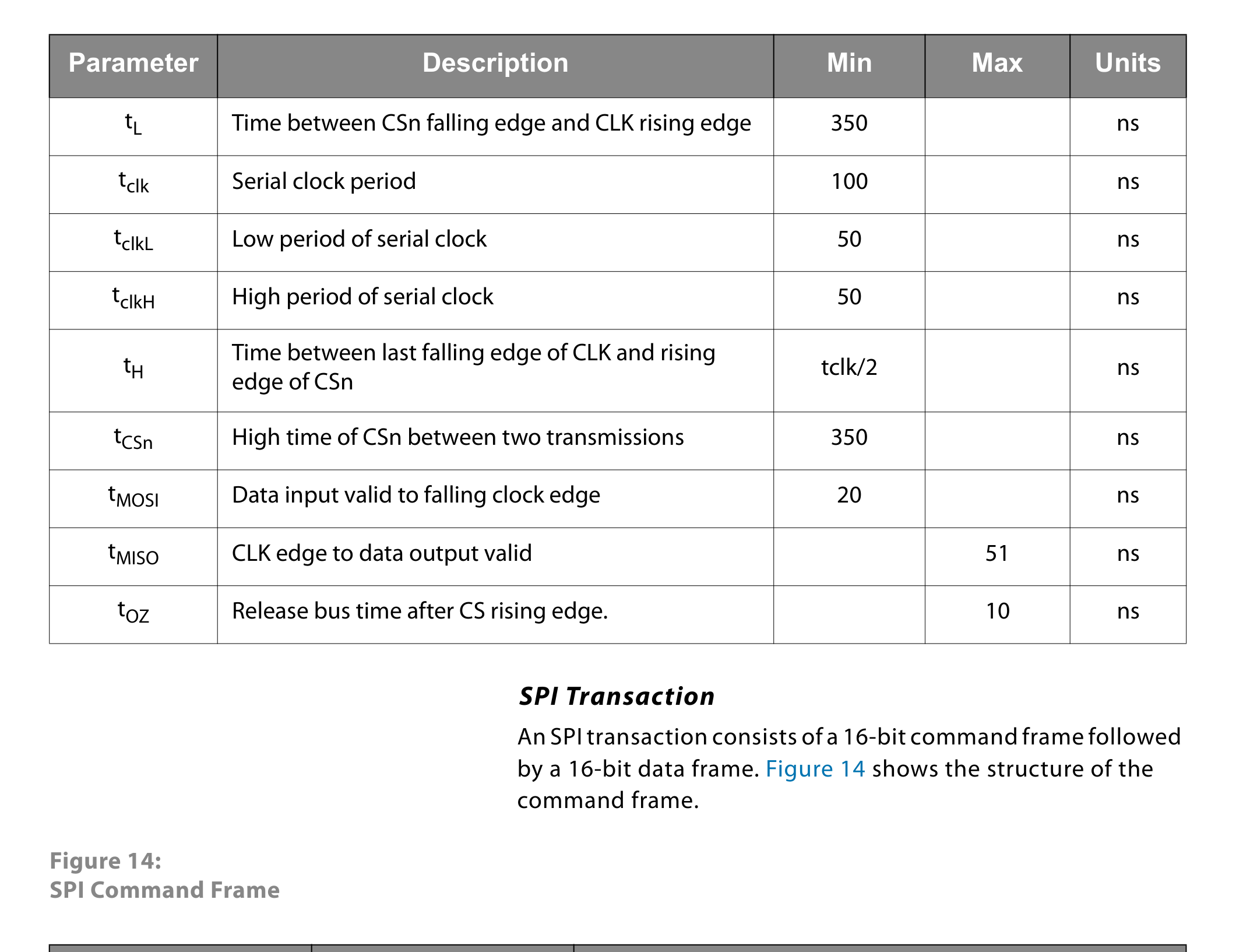
Standard 4-wire SPI. The host MCU reads 14-bit absolute angle data from the sensor and can program non-volatile settings via SPI commands — no dedicated programmer required.
ABI (Incremental)
Standard ABI incremental output signals (A, B, I/index) provided on dedicated pins. Resolution is 11-bit (2048 pulses per revolution).
UVW (Commutation)
3-phase commutation outputs U, V, W for BLDC motor commutation.
PWM
PWM-encoded angular output on I pin (index) or W/PWM pin, selectable.
Software API
Diagnostics available to the host:
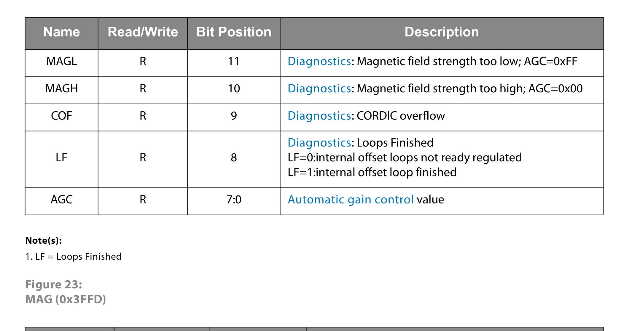
- CORDIC overflow
- Out-of-range magnetic field strength
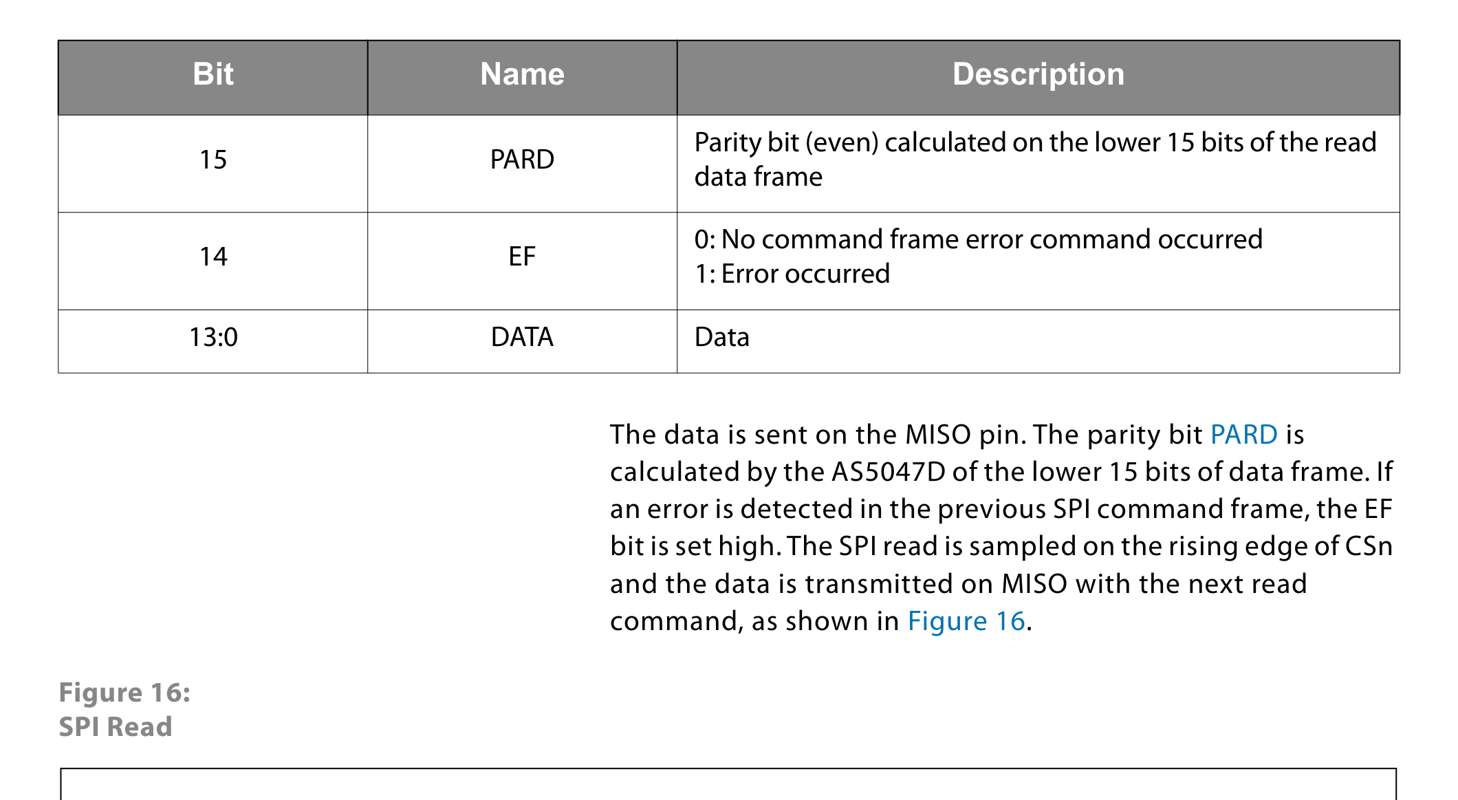
- Error flag
- Cyclic redundancy check (CRC) on SPI frames
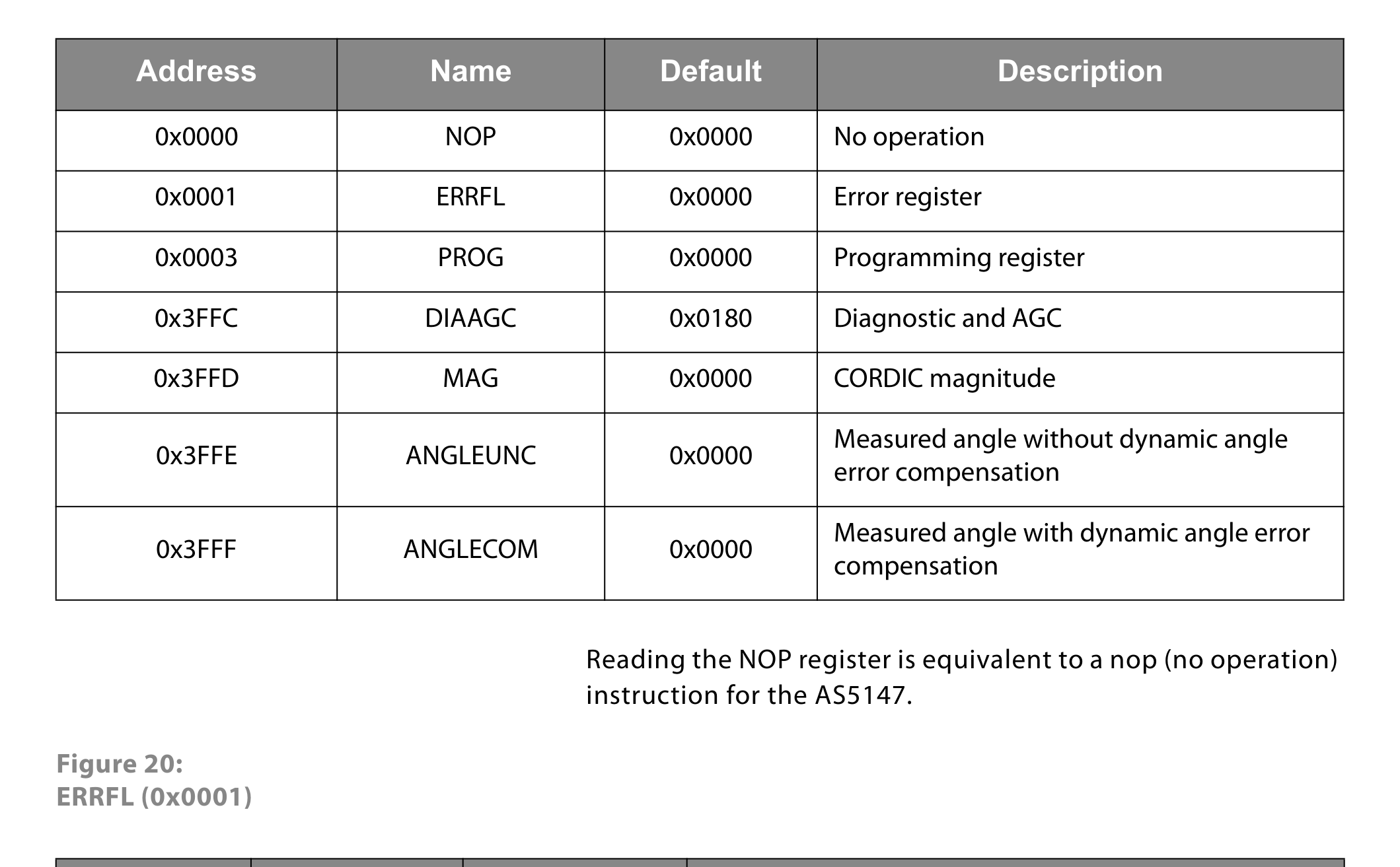
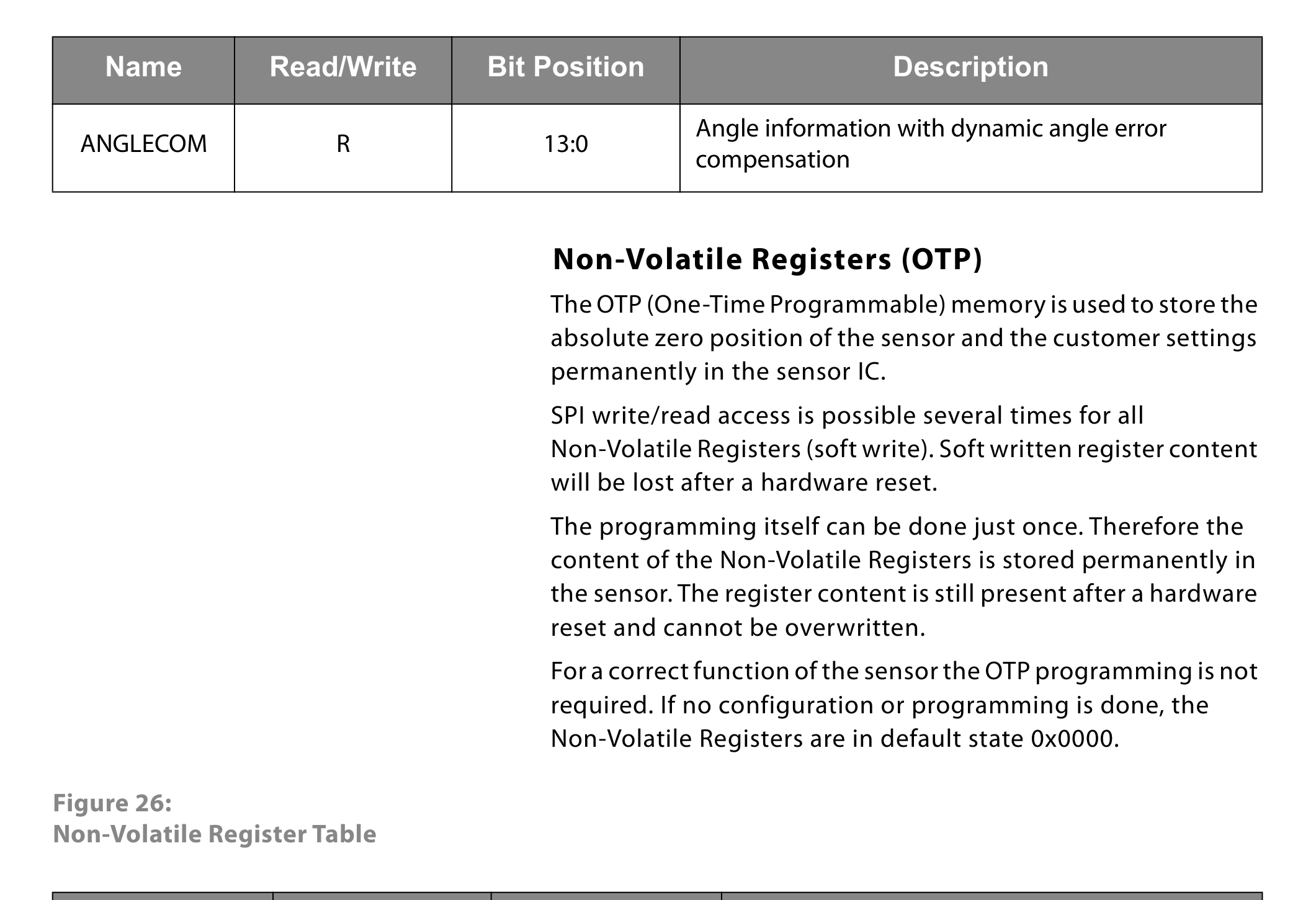
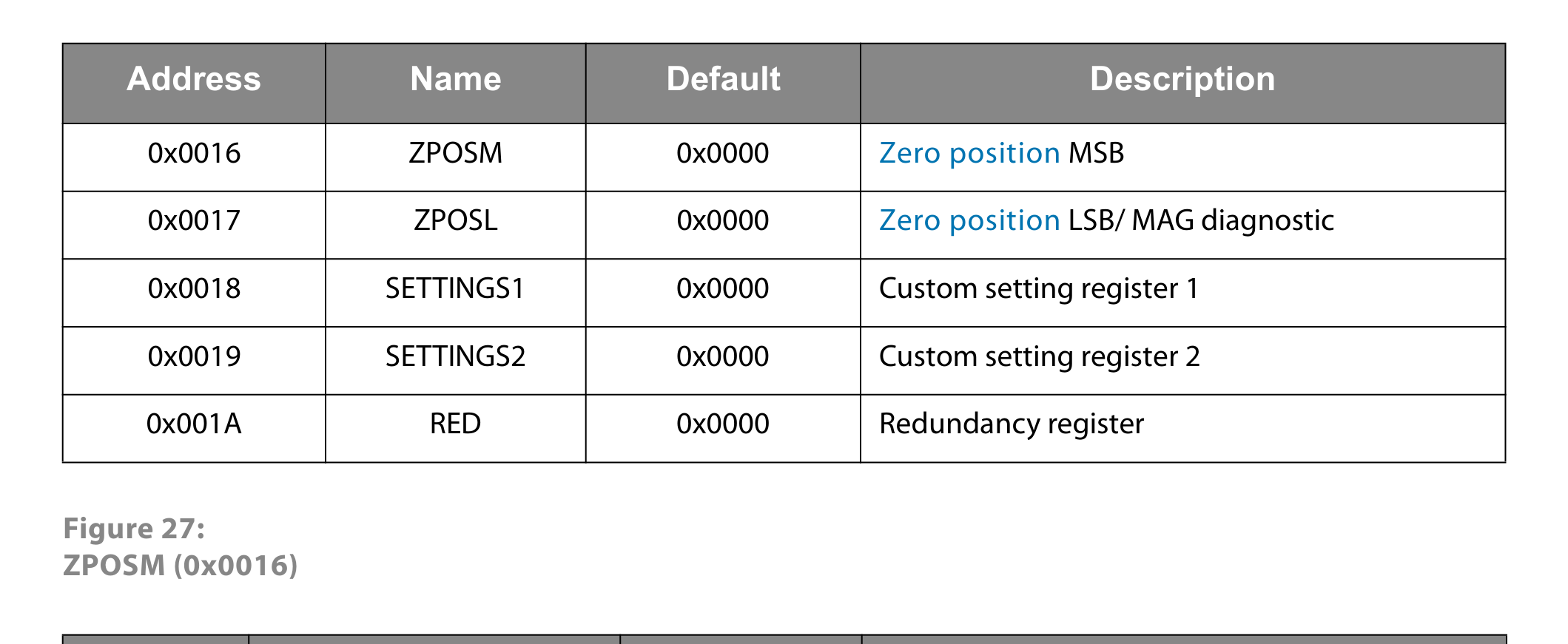
Zero position, configuration, and several operation modes are programmable via SPI commands and stored non-volatile.
Packages
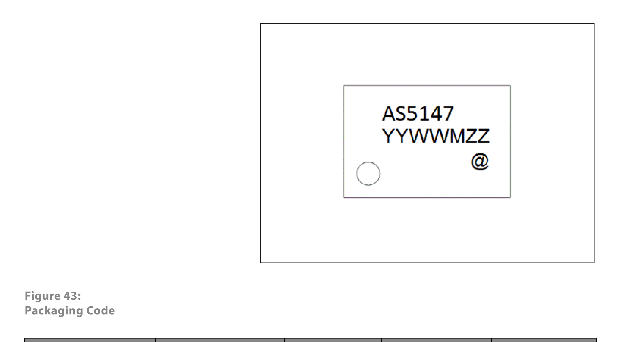
TSSOP-14 (see Figure 43 packaging code). The package is AEC-Q100 Grade 0 automotive qualified with moisture sensitivity level 3.