Bryan LED Nameplate
Public Unreviewedby John Lauer
USB-C-powered desk nameplate: spells BRYAN in 56 white 0402 LEDs on a 128x58mm board. No microcontroller — each LED wires to VBUS through its own 180 ohm current-limiting resistor. Plug in any iPhone USB-C charger and it lights up. Built as an Adom molecule with 4 corner machine-contact pins.
| Name | Last updated |
|---|---|
| js | 1mo ago |
| viewer | 1mo ago |
| 3d.glb | 1mo ago |
| 3d.png | 1mo ago |
| adom.css | 1mo ago |
| bryan-led-nameplate-source.tar.gz | 1mo ago |
| circuit.json | 1mo ago |
| favicon.svg | 1mo ago |
| index.html | 1mo ago |
| page.json | 1mo ago |
| pcb.png | 1mo ago |
| pcb.svg | 1mo ago |
| plan.md | 1mo ago |
| readme.html | 1mo ago |
| README.md | 1mo ago |
| schematic.png | 1mo ago |
| schematic.svg | 1mo ago |
| walkthrough.json | 1mo ago |


Bryan LED Nameplate
A USB-C-powered desk nameplate that spells BRYAN in 56 individual white LEDs — each letter physically drawn out of the lights. Plug any iPhone USB-C charger into the east edge and the whole name lights up. No microcontroller, no firmware, no setup. Built as an Adom molecule so it fixtures into the standard workcell via four corner machine-contact pins.
For AI handoff: this page is the canonical writeup. Everything needed to continue work — circuit decisions, BOM, build commands, file layout, known issues — is here. Source lives on the container at
/home/adom/project/bryan-led-nameplate/.
Live 3D viewer
The 3D Model viewer at the top of this page is the full interactive board —
orbit with the mouse, zoom, and inspect the assembled molecule. A standalone
copy of the adom-tsci viewer (with the Walkthrough Demo, Components / Nets HUDs,
and Inspect / Measure tools) is bundled in the repo at
index.html — open it directly
for the full toolset.
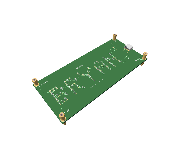
How it works
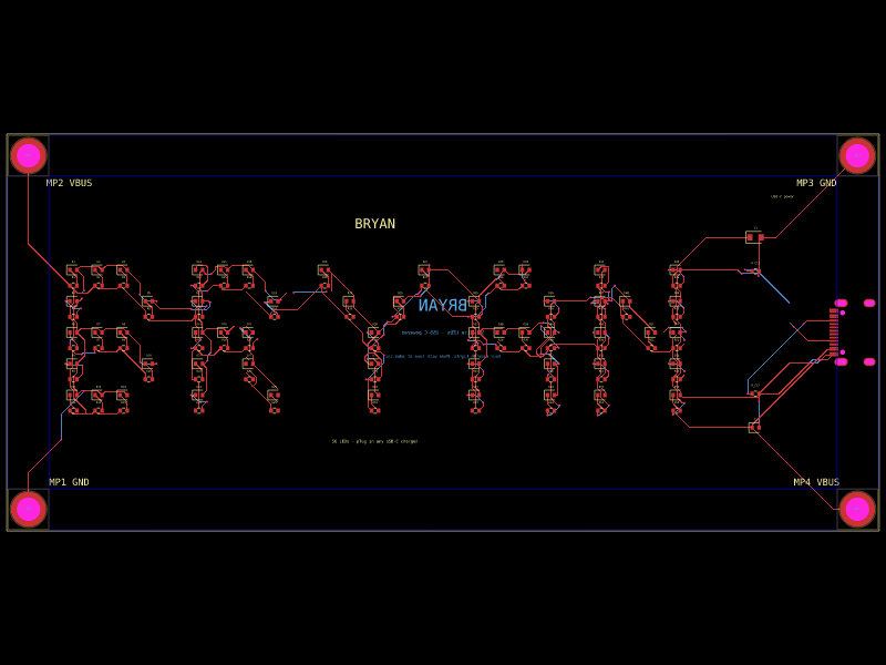
Each letter is a 5-row dot-matrix of LEDs — one <led> per lit pixel of the
B-R-Y-A-N bitmap. The font is a small bitmap embedded in lib/index.tsx as a
FONT const; the renderer walks each glyph's pixels and emits one LED + one
series resistor per lit pixel, laid out on a 3.7 mm × 4.6 mm grid.
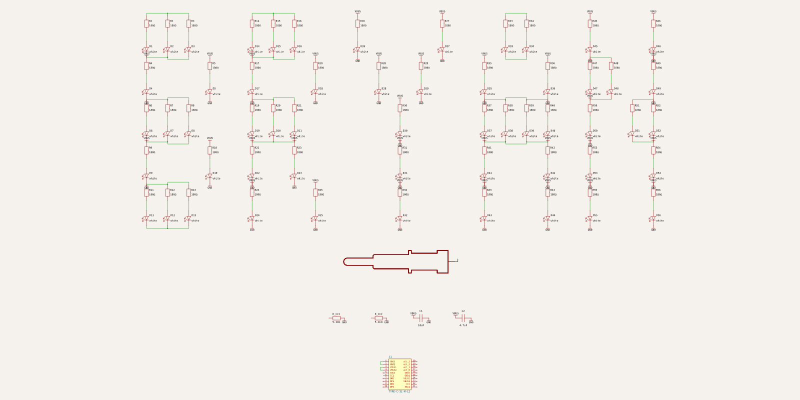
Every LED has its own 180 Ω current-limiting resistor in series, co-located just below it so the anode trace stays ~2 mm short. That keeps the space between letters free for VBUS/GND distribution and gives the autorouter a clean board. All LED+resistor pairs are wired in parallel between VBUS and GND, so a single open LED never darkens its neighbours.
The letters themselves are the power indicator — glowing means 5 V is present. There is no separate status LED.
The schematic mirrors the same grid — each cell is VBUS → 180 Ω → white LED → GND, with the USB-C receptacle, the two 5.1 kΩ CC pull-downs, and the decoupling caps below the array:
Hardware summary
| Block | Part | JLCPCB | Notes |
|---|---|---|---|
| LEDs | white 0402 × 56 | — | one per lit pixel of the BRYAN bitmap; Vf ≈ 3.2 V |
| Resistors | 180 Ω 0402 × 56 | — | one per LED, sets ~10 mA at 5 V |
| USB-C receptacle | TYPE-C-31-M-12 | C165948 | east edge, mouth cantilevered off the board |
| CC pull-downs | 5.1 kΩ 0402 × 2 | — | required for a USB-C source to deliver 5 V |
| Decoupling | 10 µF 0603 + 4.7 µF 0402 | — | smooths inrush as all 56 LEDs light together |
| Workcell pins | 4 × machine contact at corners | — | MP1/MP3 = GND, MP2/MP4 = VBUS |
Power budget: 56 LEDs × (5 V − 3.2 Vf)/180 Ω ≈ 10 mA each ≈ 0.56 A @ 5 V (~2.8 W) — comfortably inside any modern iPhone USB-C brick (20 W), and fine even on a legacy 5 W (1 A) adapter.
Mechanical
- Board: 128 × 58 mm, FR4, 2-layer, absolute-sized molecule (round edges off so the large corner pins fit).
- USB-C: east edge at
pcbX = W/2 − 4per the adom-usbc rule — SMT pads ~6.5 mm inside the edge, plated anchor holes clear of the edge, and only the plastic body/mouth cantilevers ~2.5 mm proud so a cable seats. - Workcell-ready: four corner machine-contact pins (MachinePinLargeStandard) wired to power, so the assembly cell can light the board up by its corners.
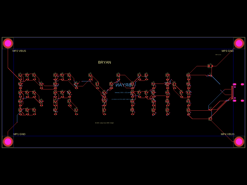
- Silkscreen: "BRYAN" caption above the letters, a USB-C power note by the connector, MP1–MP4 corner net labels, and a bottom-side dedication.
KiCad 3D models
Exported to KiCad with a (model …) reference injected for all 121
footprints (tscircuit's KiCad export omits them):
| Component | Model |
|---|---|
| LEDs / resistors / caps | KiCad standard library (LED_SMD, Resistor_SMD, Capacitor_SMD) |
| USB-C (J1) | Connector_USB/USB_C_Receptacle_HRO_TYPE-C-31-M-12 — shipped as a sidecar STEP because it isn't in the stock packages3D distribution |
| Machine pins | Adom MachinePinLargeStandard.step (sidecar) |
Note: the HRO USB-C STEP is missing from a stock KiCad install's packages3D, so a
${KICAD*_3DMODEL_DIR}/…reference renders an invisible connector. Ship the STEP alongside the board and use a relative./model path.
Source layout
bryan-led-nameplate/
  lib/
    index.tsx              ← board source — FONT bitmap, layout, traces
    UsbCReceptacle.tsx     ← TYPE-C-31-M-12 wrapper with rotation-aware cadModel
  package.json
  tscircuit.config.json
  tsconfig.json
  walkthrough.json         ← Walkthrough Demo steps (auto-generated)
  plan.md                  ← design brief
  .npmrc
  dist/lib/index/          ← build output (circuit.json, 3d.glb, pcb.svg, schematic.svg)
Build commands
cd bryan-led-nameplate
bun install                                            # once
bunx tsci build lib/index.tsx --glbs --svgs --3d-png --pcb-png
adom-tsci lint                                         # geometry + routing checks
adom-tsci start .                                      # interactive preview
Color options
Rendered in white. Any color works with the same circuit (swap the LED part and retune the resistor for the new Vf):
| Color | LED Vf | Suggested R @ 10 mA |
|---|---|---|
| Red | ~2.0 V | 300 Ω |
| Green | ~2.1 V | 270 Ω |
| Blue | ~3.0 V | 180 Ω |
| White (current) | ~3.2 V | 180 Ω |
Edit the <led color=…> and resistor value in lib/index.tsx, rebuild, re-export.
How to power it
- Grab any USB-C cable — phone charger, laptop, USB-C wall wart.
- Plug it into the east edge of the board.
- Plug the other end into a 5 V USB-C source.
- BRYAN lights up.
Known issues / lessons learned
- USB-C GND pad clearance: the two end GND pads of the TYPE-C-31-M-12 footprint sit 0.3 mm apart, which trips a 0 mm pad-clearance DRC note. Both are GND (same net), so it's electrically harmless — inherent to the connector footprint.
- Schematic machine-pin pile:
<Molecule>emits MP1–MP4 at the schematic origin and they can't be placed from the board source, so a schematic-overlap lint flag is expected. Cosmetic only; the PCB is unaffected.
Talk to the AI
- Open / view: "Open the live 3D viewer", "show the BRYAN board in 3D", "open the PCB view"
- Inspect: "Click any chip to see refdes + footprint", "measure pin to pin"
- Run: "Run the Walkthrough Demo", "re-run the autorouter"
- Fab: "export the gerbers", "open this in KiCad", "run DRC"
Files attached
Source — recreate the molecule:
- plan.md — design brief, refinements, out-of-scope notes
- bryan-led-nameplate-source.tar.gz — full tscircuit project source
Build outputs:
- 3d.glb — full 3D model
- pcb.svg — flat PCB layout (vector)
- schematic.svg — circuit diagram

Build provenance
Built with adom-tsci, Adom's tscircuit
board viewer. Walkthrough auto-generated from circuit.json.
Designed by Adom in Fort Worth, Texas.