Adom Custom Electronic Load
Public Made by Adomby adom
Two-layer digitally controlled electronic-load prototype. Compact R11 is under active electrical, cooling and probe-access review; not a manufacturing release.


Three compact coolers — 3D heat spreading and conditional power
Open the interactive thermal comparison · Original assembly mockups · Q1 and diode alternatives
This study now solves heat conduction in three dimensions through an equivalent Q1 case, AlN isolator, spreader, heatsink base and fins. It uses a development extension to Adom Fields, rather than just a board-surface thermal texture. Calculated temperatures are not measurements or qualified power ratings. The compact PCB remains an unrouted 72 × 72 mm packing target with large pins on a 64 × 64 mm grid; the thermal model does not establish probing clearance.
What the three options can potentially dissipate
All comparisons retain 40°C ambient, the 55°C case ceiling, the existing stricter 55°C junction screening ceiling and a 10% power guard. All DUT power is conservatively assigned to Q1. The current firmware remains limited to 5 W.
| Cooling concept | Nominal cooler envelope | Fan-off assumptions, h=5–10 | Moving-air assumptions, h=50–150 | At h=100, refined mesh |
|---|---|---|---|---|
| Preferred low-profile | 50 × 50 × 12 mm | 0.69–1.28 W | 4.03–6.28 W | 5.53 W |
| Taller chipset fins | approximately 40 × 40 × 45 mm with fan | 1.85–3.12 W | 6.86–8.64 W | 8.12 W |
| Pi 5 blower concept | 42.5 × 63.5 × 13.7 mm | 0.90–1.64 W | 4.78–7.04 W | 6.32 W |
h is an assumed surface convection coefficient in W/m²K, not a measured fan speed or airflow. These are sensitivity ranges, not confidence intervals or product ratings. The larger fin stack leads this particular model at the cost of height. The flatter two remain candidates for approximately 5 W, conditional on installed cooling, a reliable clamp and retained protection. None supports 5 W continuously in the modeled fan-off range. Fan failure must trigger shutdown or a separately qualified reduced-power mode; these steady-state results cannot set shutdown timing.
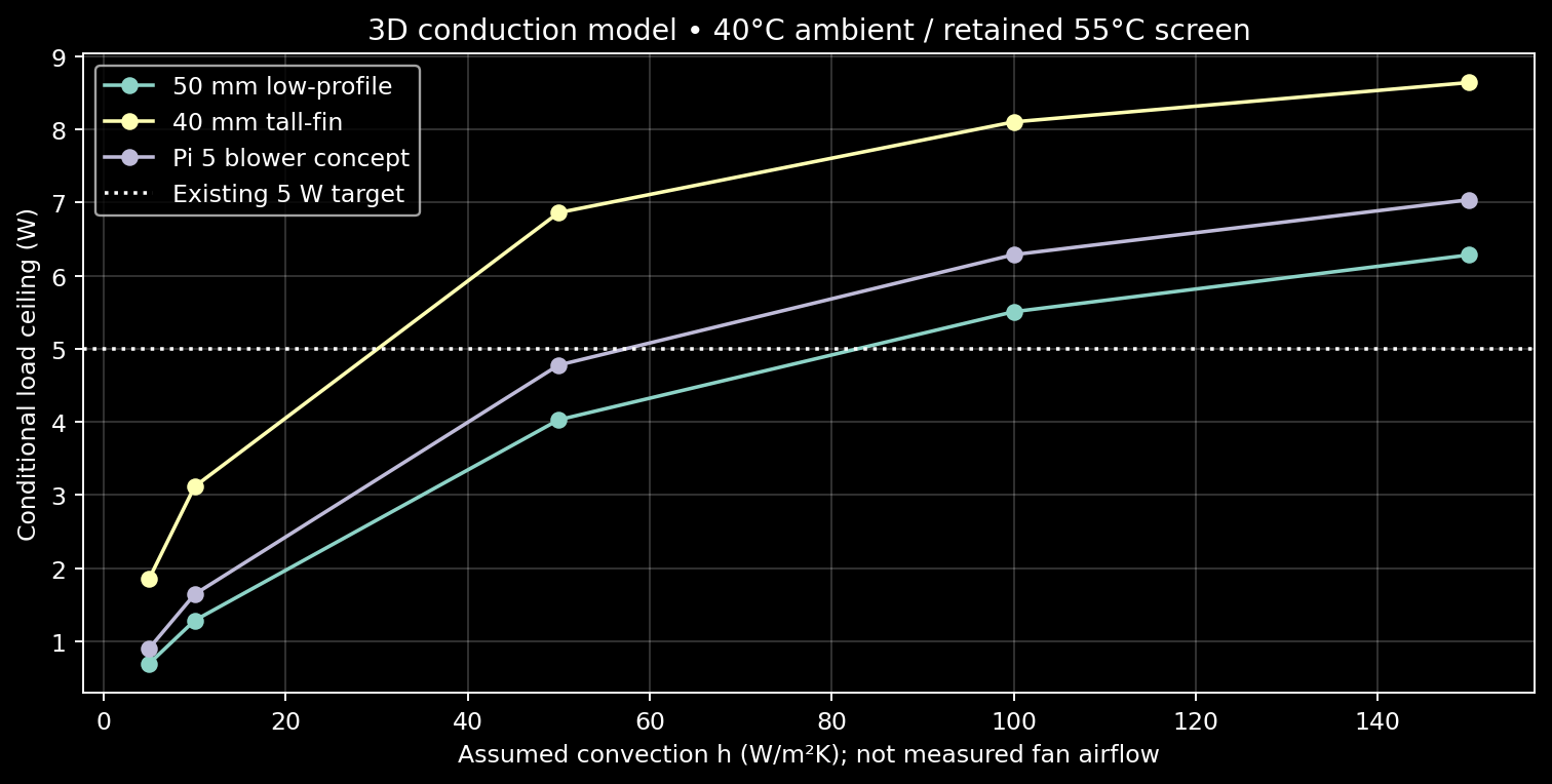
At h=100 and 5.5 W heat input, the refined results are:
| Concept | Hottest modeled case | Estimated junction | Heatsink temperature span |
|---|---|---|---|
| Low-profile | 51.25°C | 53.56°C | See numeric results/viewer |
| Tall-fin | 46.92°C | 49.23°C | See numeric results/viewer |
| Pi-style | 49.56°C | 51.87°C | See numeric results/viewer |
Junction is conservatively estimated as the hottest equivalent case cell plus Q1 power × 0.42 K/W. The silicon die and molded package are not resolved. The fan-off viewer holds 5.5 W constant to illustrate a failed-shutdown scenario, not normal authorized operation. It is a steady endpoint, not a transient warm-up simulation; no time to failure is claimed.
Where the heat goes
The viewer lets you hide the heatsink and then the interface layers to inspect Q1. It loads one model at a time. A shared 40–150°C colour range compares fan assumptions; the optional 40–60°C magnification reveals the smaller operating gradients and explicitly saturates hotter cells. Numeric extrema are always shown.
The following cross-sections show temperature and conductive heat flux. Arrows show direction, not speed. Flux is estimated from the solved neighbouring-face transfers; it is not a measured silicon heat-density map. The equivalent case source distributes its prescribed power uniformly.
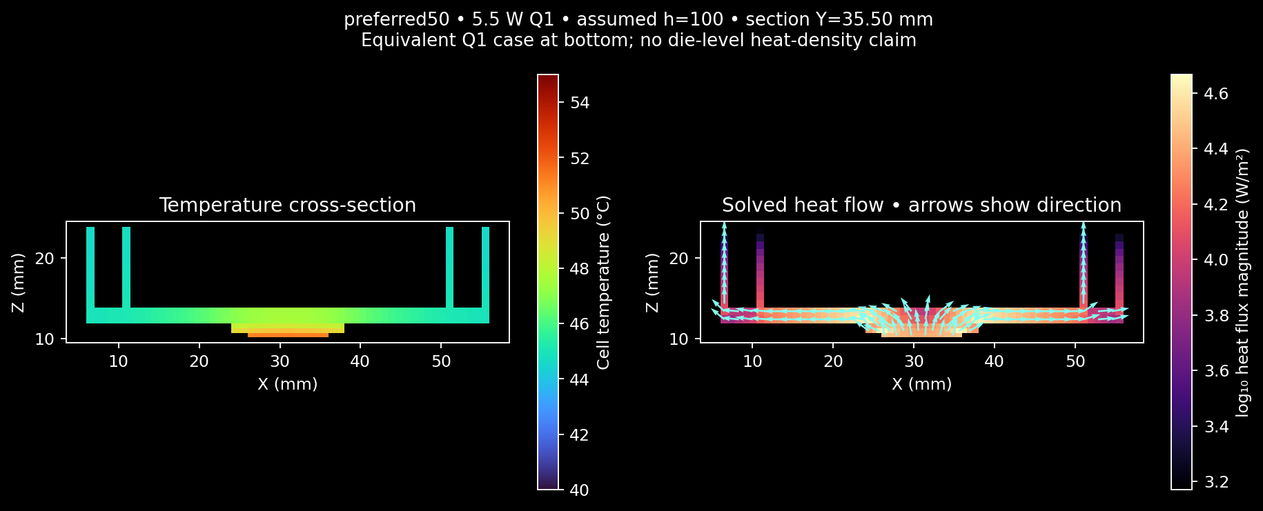
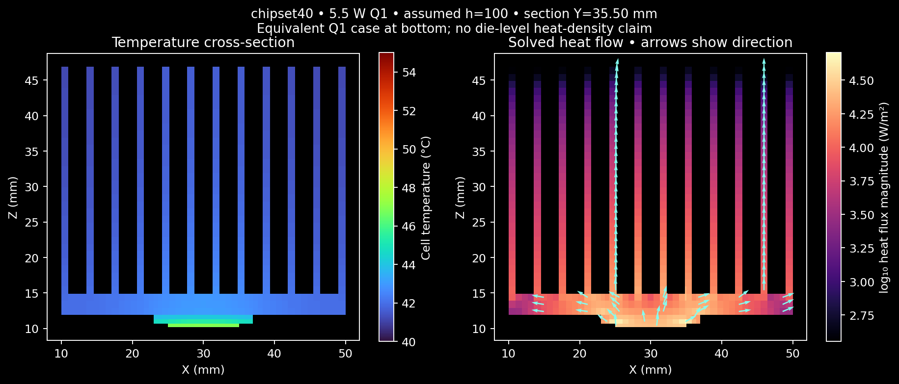
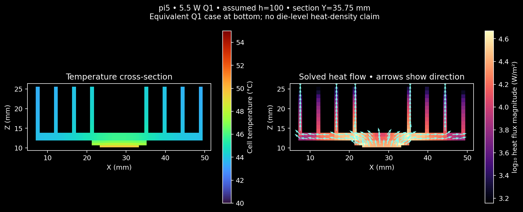
Heat flows from the local Q1 contact into the wider base and then up the fins. There is no arbitrary spreading-resistance term: spreading follows the modeled volumes. Unlike the earlier fin-efficiency estimate, exposed surfaces are counted from actual concept boxes. That difference changes the effective area, so the older and newer results are not an independent validation of one another.
Assumptions and numerical checks
- Approximate fin geometry comes from our concept GLBs' source primitives, not measured or manufacturer-verified internal geometry. Their external envelopes have the source references in the size study.
- Nominal conductivities: aluminium 200, copper 385, AlN 170 W/mK. These are constant modeling assumptions, not supplier certificates. Contact interfaces retain a distributed effective allowance equivalent to the earlier 0.6728 K/W nominal budget; solid-layer conduction is additionally modeled. The concept's thinner spacer has not been qualified.
- Only exposed heatsink sides and top surfaces convect. Underside and package edges are insulated. No PCB cooling credit, radiation, recirculation, airflow pressure solution, fan motor heat, heat pipes or transient thermal mass is included. This is solid conduction with supplied boundaries, not CFD.
- Five h values were solved per concept at 2 mm maximum cell pitch. The h=5 and h=100 cases were repeated at 1 mm. Every geometry boundary remains in the nonuniform grid, including thin interfaces and fins.
- All 21 solves converged with relative residual below 1e-10 and relative energy error below 1e-6. Mesh refinement changed the compared power ceilings by less than 0.5%. This checks numerical consistency, not the accuracy of assumed geometry and convection.
- The source build passed 26 tests, including analytical slab, contact drop, insulated island, overlap, unknown contact, zero heat and mesh-refinement tests; production check and optimized build passed. The installed shared Fields release was not replaced.
Numeric summary and exact solver executable hash. Full refined fields: low-profile on, low-profile off, tall-fin on, tall-fin off, Pi-style on, Pi-style off. Each includes exact input geometry, assumptions, SHA-256, temperatures and signed face heat flows.
Reproduce using tools/build_volume_study.py <path-to-development-adom-fields> and tools/plot_volume_study.py. Source inputs are under analysis/cooling-volume/. The GLB exporter is part of the proposed Fields extension.
Component selection and next hardware decision
The parts review keeps IXTP15N50L2 and SBR10U45SP5-13 as the reference. An ideal diode could remove much of D1's PCB hotspot, but at fixed DUT power that heat moves mostly into Q1. This cooler screen already assigns all DUT power to Q1, so it does not claim an ideal diode improves total heat rejection. The alternative still needs startup/reverse-fault, loop-stability, leakage, sourcing and PCB-area review.
No higher-power board rating is released: DC safe operating area, D1/shunt/trace losses, sensing and protection, fan tach, installed airflow, supplier geometry, probe access and actual temperature measurements remain required. Commercial CPU-cooler marketing wattage cannot replace these checks.
Shared Fields source status
Fields source PR #12 and owner issue #12 track the reusable capability. The focused branch is based on fbce2638ab91b76cf34f802c5a10a11cfeaaecc8; the submitted diff matches the reviewed six-file patch. Source tests, optimized build and native project-viewer checks passed. Owner merge, package publication and installation are pending. The shared installed Fields binary was not replaced.
Recorded analysis
Five native Pup clips cover the solid heat path, fan-off sensitivity, low-profile cooler, Pi-style concept and comparison. They are edited with separately generated Adom TTS narration into the updated 4:34 project video, starting at 3:26.8. New captions are sentence-level timing estimates, not forced-aligned words. No hardware measurement is portrayed.